
Statistical calibration of wireless base stations

a wireless base station and statistical technology, applied in the field of digital signal communication and to receive and transmit chain calibration, can solve the problems of reducing the effectiveness of directionally transmitting coherent gain toward desired remote user terminals, nulls to interfering remote user terminals, and usually not being able to accurately calibrate a system in the factory, so as to reduce the cost of additional equipment and the difficulty of locating the calibration antenna

Inactive Publication Date: 2006-01-03
INTEL CORP
View PDF7 Cites 47 Cited by
  • Summary
  • Abstract
  • Description
  • Claims
  • Application Information

AI Technical Summary

Benefits of technology

[0015]In general, the present invention collects data from regular remote user terminal calls initiated as part of normal operations in order to passively calibrate the receive section for each base station antenna of a multiple antenna array. This feedback from the remote user terminals can include received signal strength measurements or signal quality measurements returned by the terminals to the base station as is done for example in GSM (Global System for Mobile Communications), or more complex measurements, such as transmit diversity data normally returned by the user terminal in the WCDMA (Wideband Code Division Multiple Access) standard. This feedback can be combined with a systematic procedure for varying the relative phases of the signals transmitted from the multiple antennas of the base station in order to calibrate the transmit section for each antenna of the base station. The calibration can be enhanced by determining which of the ‘passive’ data is valid to use in calibrating the receive and transmit sections. The calibration can be further enhanced by applying statistical methods to extract the most reliable feedback calibration data for the transmit and receive sections.

Problems solved by technology

These calibration vectors tend to change slowly over time due to environmental changes such as temperature, and also over frequency bands, but can change so much that unless they are taken into account, signals transmitted from an antenna array will emanate from each antenna with unknown phase, and therefore reduce the effectiveness of directionally transmitting coherent gain toward desired remote user terminals or nulls to interfering remote user terminals.
Since the phase and amplitude response of both the receive and transmit sections depends upon installation-specific items such as cables, connectors, antennas, etc., it is usually not possible to accurately calibrate a system in the factory.
This adds the cost of the additional equipment as well as the difficulty in locating the calibration antenna.
However this method may not work with some directional antenna systems, such as sectorized antenna systems.

Method used


Image

  • Statistical calibration of wireless base stations
  • Statistical calibration of wireless base stations

Examples


Embodiment Construction

[0011]Introduction

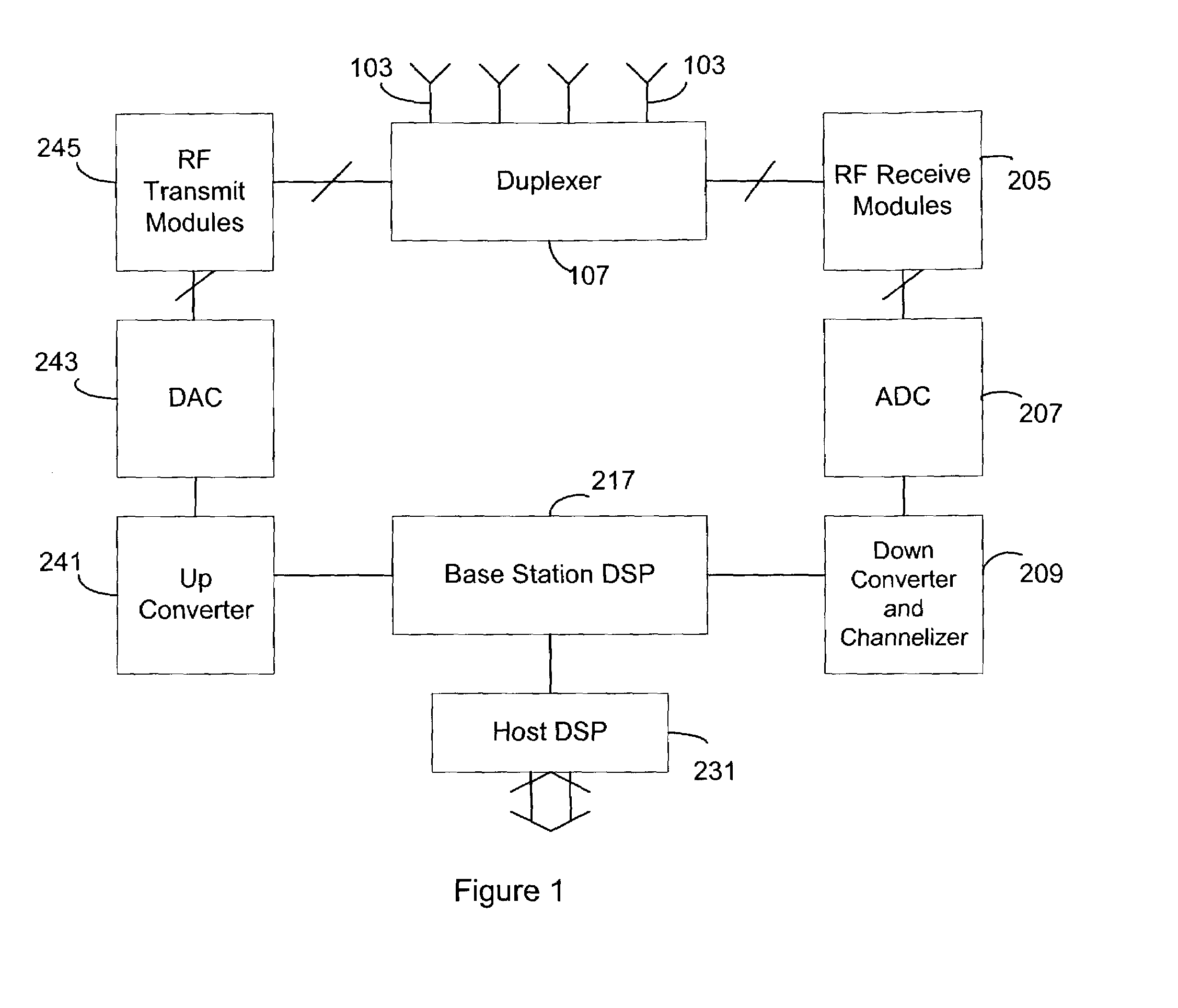
[0012]In one embodiment, the present invention is implemented in a Spatial Division Multiple Access (SDMA) radio data communications system as shown and described further with respect to the FIG. 1. In such an SDMA system, each terminal is associated with a set of spatial parameters that relate to the radio communications channel between, for example, the base station and a user terminal. The spatial parameters comprise a spatial signature for each terminal. Using the spatial signature and arrayed antennas, data can be sent to several different user terminals at the same time using the same radio frequency band. Conversely, data can be received from several different user terminals at the same time on the same radio frequency band. In a CDMA system, SDMA can lower the noise floor for subscribers that are spatially separated from one another. The spatial signatures allow the otherwise colliding or interfering signals to be resolved. The spatial signatures can includ...


PUM


Abstract

The present invention allows a radio receiver or a transmitter, with a plurality of antennas configured into an array, to be calibrated. In one embodiment, the method includes receiving a plurality of signals from a plurality of remote transmitters at the antenna array, sampling the signals received at at least two antennas of the array, computing a relative phase and amplitude of the sampled signals for each antenna, and computing calibration coefficients based on the relative phase and amplitude for the plurality of sampled signals from the plurality of remote transmitters for each antenna.

Description

CROSS REFERENCE TO RELATED APPLICATIONS[0001]This application claims the benefit of U.S. Provisional Patent Application Ser. No. 60 / 309,448 for Statistical Calibration of Wireless Base Stations, to inventors Da Torre, Parish, Kasapi, Lindskog, Trott and Kerr, Assignee ArrayComm, Inc., filed Jul. 31, 2001.BACKGROUND OF THE INVENTION[0002]1. Field of the Invention[0003]The invention relates generally to the field of digital signal communications and to receive and transmit chain calibration. More particularly, the invention relates to calibrating a wireless base station using statistical operations on an accumulated set of received signals.[0004]2. Description of the Related Art[0005]Radio communications capacity can be greatly increased using directional, rather than omnidirectional radio transmission. One way to transmit directional signals and directionally receive signals is by using beam forming and nulling through an array of antennas. The precision of the beam forming and nulli...

Claims


Application Information

Patent Timeline
IPC IPC(8): H04B17/00
CPCH04B17/20H04B17/10H04B7/04H04B7/0634
Inventor DA TORRE, SERGE BARBOSAPARISH, DAVID M.KASAPI, ATHOSLINDSKOG, ERIK D.TROTT, MITCHELL D.KERR, ADAM B.
Owner INTEL CORP
Learn More