Deskewed differential detector employing analog-to-digital converter

a technology of analog-to-digital converter and differential detector, which is applied in the field of differential detectors, can solve the problems of misaligning the complementary edges of a differential signal, affecting the accuracy of the input signal test system, and posed new and difficult challenges for ate manufacturers, and achieves the effect of effectively offs

Inactive Publication Date: 2005-12-27
TERADYNE
View PDF4 Cites 9 Cited by
  • Summary
  • Abstract
  • Description
  • Claims
  • Application Information

AI Technical Summary

Benefits of technology

[0014]With the foregoing background in mind, it is an object of the invention to reduce timing skew between different legs of differential signals.

Problems solved by technology

Testing differential signals at these high speeds has posed new and difficult challenges for ATE manufacturers.
Even minute differences in the lengths or electrical characteristics of fixture wires or other parts of an ATE system can misalign the complementary edges of a differential signal.
Changes in signal shape prevent a test system from accurately measuring certain characteristics of input signals, such as edge speeds and ringing.

Method used


Image

  • Deskewed differential detector employing analog-to-digital converter
  • Deskewed differential detector employing analog-to-digital converter
  • Deskewed differential detector employing analog-to-digital converter

Examples


Embodiment Construction

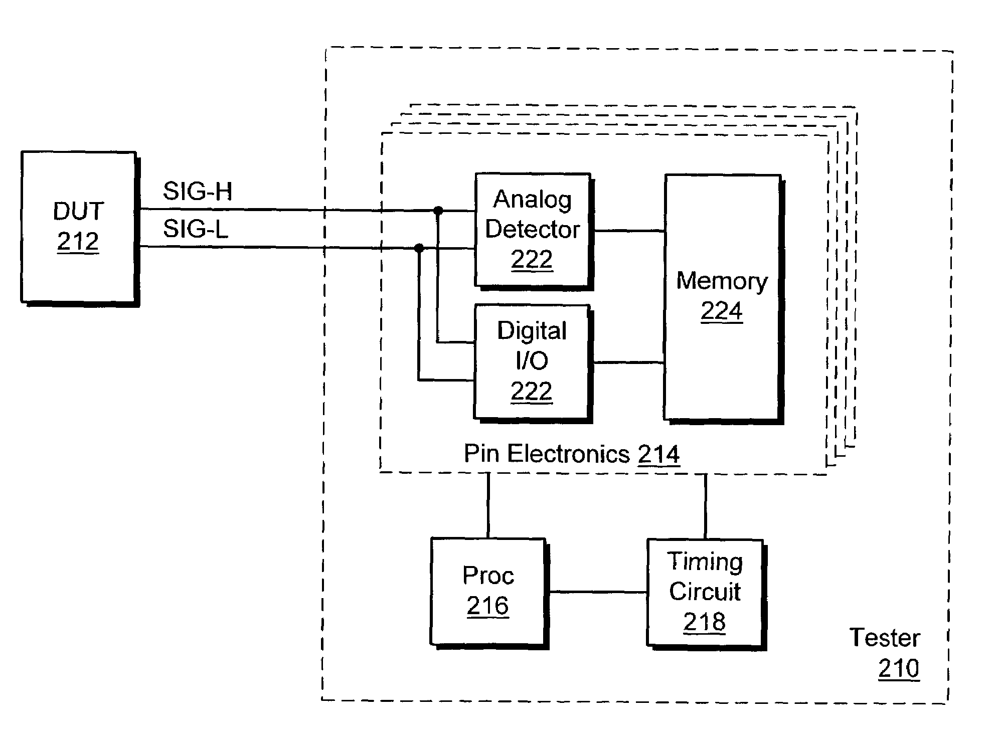
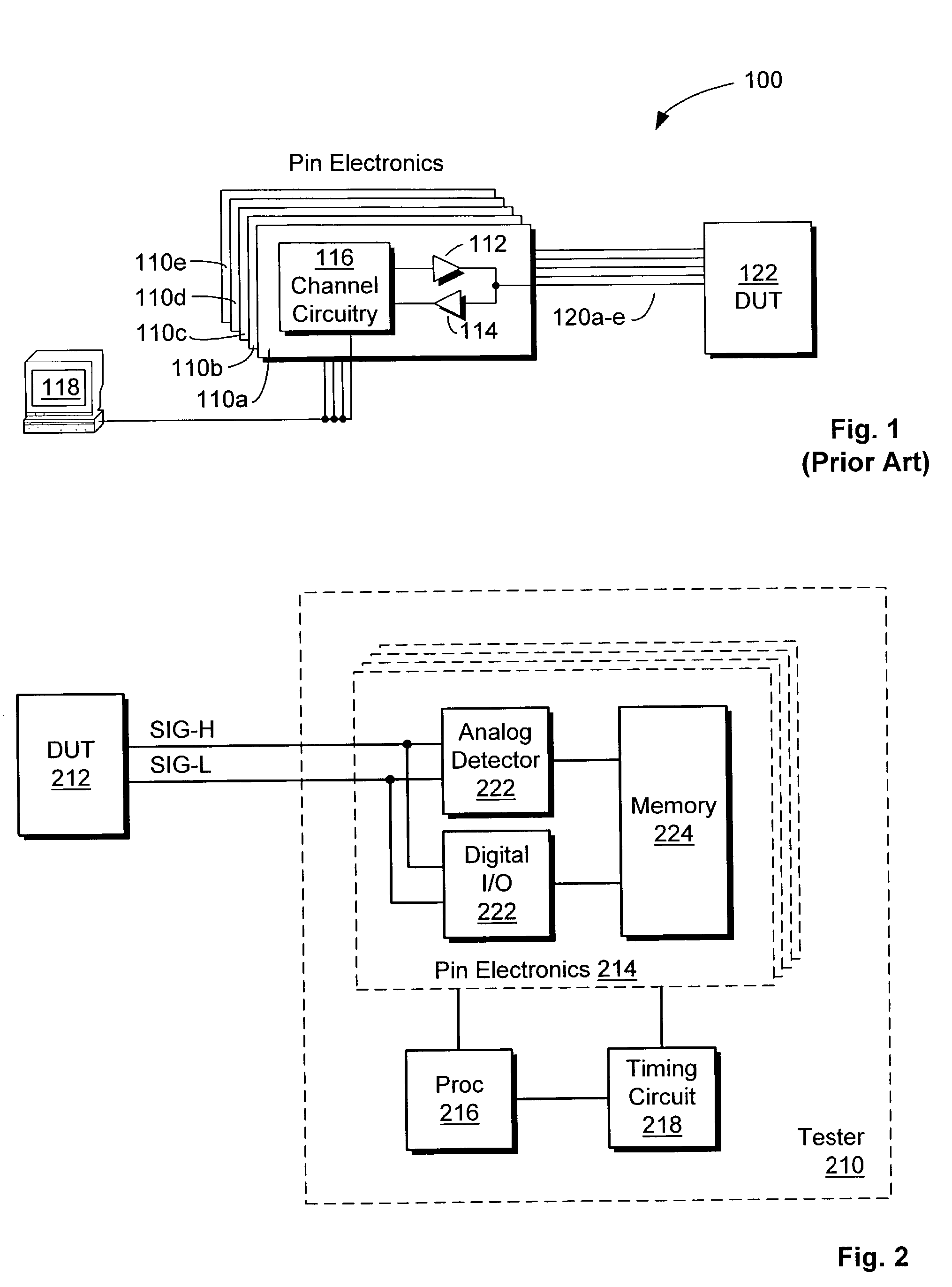
[0026]FIG. 2 shows a simplified block diagram of a tester 210 constructed in accordance with an embodiment of the invention. The tester 210 is arranged for testing differential signals produced by devices under test, such as DUT 212. An illustrative differential signal includes a first leg, SIG-H, and a second leg, SIG-L. The first and second legs of the differential signal vary in opposition with each other. The differential signal is conveyed to a pin electronics channel 214 within the tester, whereupon the signal is inputted to an analog detector 220. The analog detector includes circuitry for sampling each leg of the differential signal. The sampled signals are preferably stored as digital values in a memory 224.

[0027]Optionally, the pin electronics may also include digital I / O circuitry 222. The digital I / O circuitry may house conventional single-ended drivers and detectors. It may also include differential comparators and common-mode comparators, similar to those described in ...


PUM

PropertyMeasurementUnit
timeaaaaaaaaaa
speedaaaaaaaaaa
speedsaaaaaaaaaa

Abstract

A pin electronics circuit for automatic test equipment includes first and second sampling circuits for sampling first and second legs of a differential signal produced by a DUT (Device Under Test). Timing signals activate the first and second sampling circuits to sample the legs of the differential signal at precisely defined instants of time to produce first and second collections of samples. To deskew the legs of a differential signal with respect to each other, corresponding features within the first and second collections are identified and a difference is taken between them. The differential skew can then be applied to correct measurements of differential signals.

Description

CROSS-REFERENCES TO RELATED APPLICATIONS[0001]Not Applicable.STATEMENT REGARDING FEDERALLY SPONSORED RESEARCH OR DEVELOPMENT[0002]Not Applicable.REFERENCE TO MICROFICHE APPENDIX[0003]Not ApplicableBACKGROUND OF THE INVENTION[0004]1. Field of the Invention[0005]This invention relates generally to detector circuits for automatic test equipment, and more particularly to detector circuits for receiving differential signals from a device under test (DUT).[0006]2. Description of Related Art[0007]Automatic test equipment (ATE) plays a significant role in the manufacture of semiconductor devices. Manufacturers generally use automatic test systems—or “testers”—to verify the operation of semiconductor devices at the wafer and packaged device stages of the semiconductor manufacturing process. By testing semiconductor devices at these stages, manufacturers are able to reject defective devices early, eliminating costs that would otherwise be incurred by processing defective parts. Manufacturers ...

Claims


Application Information

Patent Timeline
Patent Type & Authority Patents(United States)
IPC IPC(8): G01R31/319G01R31/3193
CPCG01R31/31924G01R31/31937G01R31/31908
Inventor PANIS, MICHAEL C.
Owner TERADYNE
Why Eureka
Try Eureka