
Communications system using chaotic synchronized circuits

a communication system and circuit technology, applied in the field of communication system using chaotic synchronized circuits, can solve the problems of cyclic path, complex circuit, and extremely long cycle-length, and achieve the effect of reducing the number of synchronized circuits

Inactive Publication Date: 2005-12-27
LEIDOS
View PDF12 Cites 36 Cited by
  • Summary
  • Abstract
  • Description
  • Claims
  • Application Information

AI Technical Summary

Benefits of technology

[0012]It is still another object of the invention to provide a method for modulating a circuit that generates a chaotic signal in a stable manner.
[0018]According to another embodiment, the invention is a communications device with a transmitting chaotic circuit configurable responsively to an information signal. The configurations are such that the transmitting chaotic circuit produces at least three different chaotic signals, each characterized by a different trajectory-versus-time characteristic. The device includes a receiver with an oscillating subportion to which the different chaotic signals can be applied to drive the oscillating subportion. The receiver has a beat detector connected to the oscillating subportion to detect a difference between a fundamental frequency of the oscillating subportion and a current chaotic signal. This allows the information signal to be detected by the detection of beats.
[0023]According to still another embodiment, the invention is a communications receiver system as described in the previous paragraph except the receiver is divided into an oscillator portion and a chaotic portion which are separately driven through emitter followers from the voltage of the communications medium. This allows the voltage of the communications medium to drive the oscillator portion and the chaotic portion of the receiver without direct feedback between the two through the synchronizing resistor. This prevents spontaneous chaotic oscillation in the receiver due to a feedback path from the chaotic portion of the Chua circuit to the oscillator portion of the Chua circuit. The circuit still synchronizes since the voltage of the communications medium is coupled to both the oscillator portion of the receiver and the chaotic portion of the Chua circuit. As a result the receiver responds only when there is a voltage on the communications medium to stimulate the system. (see FIG. 4e).
[0024]According to still another embodiment, the invention is a communications receiver system divided into an oscillator portion and a chaotic portion. The oscillator portion is driven by the voltage of the communications medium. The voltage of the chaotic portion is fed back to the oscillator portion through an emitter follower and the synchronizing resistor in a phase lock loop type arrangement. This allows the voltage of the communications medium to drive the oscillator portion and the voltage of the chaotic portion of the receiver to directly feedback through the synchronizing resistor to quickly synchronize the communications system in the presence of a voltage on the communications channel. This arrangement rapidly synchronizes the communications system. The circuit still synchronizes since the voltage of the communications medium is coupled to the oscillator portion of the receiver and the chaotic portion of the Chua circuit feeds back a portion of the receiver voltage. As a result, the receiver responds only when there is a voltage on the communications medium to stimulate the system (see FIG. 4f).

Problems solved by technology

Chaotic systems evolve deterministically, and, their chaotic state paths are cyclic, but very complex and with extremely long cycle-lengths.
In real systems, however, with extremely long cycle periods, it may be of little practical significance that their behavior is cyclical because the physical systems that generate the behavior may not be sufficiently stable for the system to ever return to the same dynamical system in its same initial state.
However, compared to oscillators, such as used to generate carriers for radio transmission, the peak is not pronounced, that is, it is very short and wide.
Prior art systems have been discussed widely, but few practical working designs are known.
Synchronization systems are inherently noisy and error prone due, at least in part, to the time it takes for synchronization to occur in a noisy channel.
Also, according to the prior art, modulation also cannot span too great a range.
Otherwise, a tightly locked synchronization, which is, according to the prior art, essential, cannot be maintained.
In addition, the practical problems attending achievement of high data throughput, the providing of reliable locking performance, and various purely practical design considerations have not received a great deal of attention.

Method used


Image

  • Communications system using chaotic synchronized circuits
  • Communications system using chaotic synchronized circuits
  • Communications system using chaotic synchronized circuits

Examples


Embodiment Construction

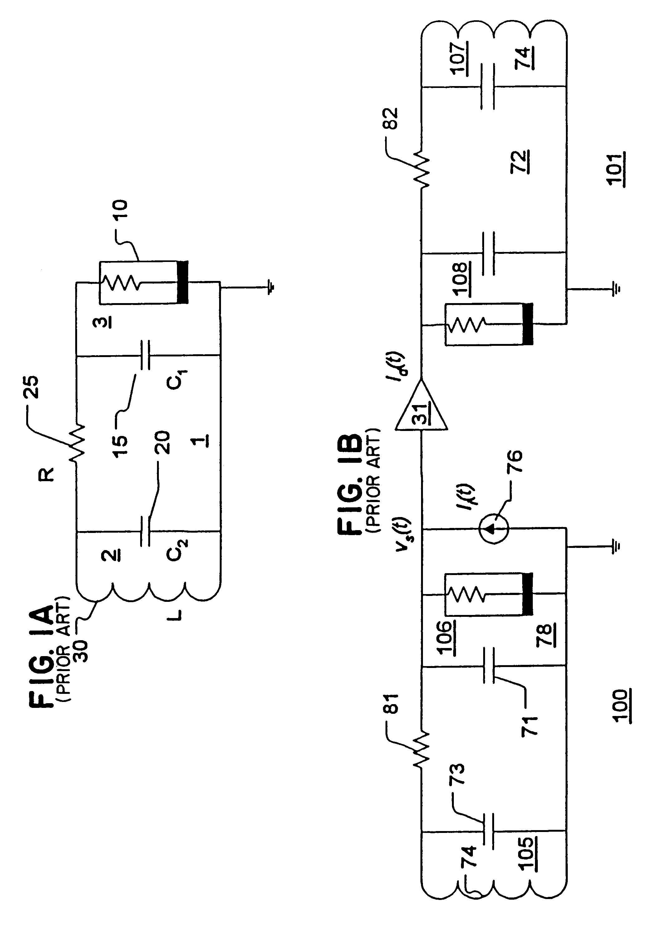
[0040]Referring again to FIG. 1D, discussed in the background, the various chaotic oscillating regimes of the Chua circuit are mapped on an α / β parameter plane. Circuits falling in a double scroll region 60 are characterized by oscillation about two strange attractor equilibrium points. Circuits falling in a spiral set of oscillating regimes 61 exhibit oscillation about only one strange attractor equilibrium point. Varying C1 causes the α / β combination to shift as indicated by arrow 130. Varying C2 causes the α / β combination to shift as indicated by arrow 140. Varying R2 or L causes the α / β combination to shift as indicated by arrow 150. As can be seen from the diagram (FIG. 1D, the capacitance C2 of capacitor 20 may be varied over a wide range while still maintaining operation of the circuit in the double scroll oscillating regime 110. A much smaller range of values of capacitance of capacitor 15 (C1) coincide with operation in the double scroll regime 60. The wide range of capacit...


PUM


Abstract

A chaotic communication system employs transmitting and receiving chaotic oscillating circuits. In an embodiment of the invention employing a Chua circuit as the basic chaotic circuit, the transmitter has a tank circuit portion and a Chua diode portion linked through a resistance. The capacitance of the tank circuit is varied by selectively switching in and out of the tank circuit an auxiliary capacitance isolated by an optoisolator. Switching of the optosiolator is controlled by an information signal to generate a perturbed oscillation in the transmitting circuit. A voltage is tapped from the Chua diode circuit and transmitted to carry the information from the information signal. A receiver in another embodiment applies the transmitted signal to both the tank circuit and Chua diode portions of the receiving circuit. The transmitted signal is applied through a resistor to the Chua diode portion as well as the tank circuit portion. By applying the received signal to the Chua diode portion as well as the tank circuit, synchronization of the transmitter with the receiver is accelerated substantially. In still another embodiment, the tank circuit components are varied to generate a vocabulary of chaotic signals that can be decoded by various receiver embodiments that are described.

Description

[0001]This application is a continuation of common-owned, U.S. application Ser. No. 09 / 116,661 (“Communications System Using Chaotic Synchronized Circuits”) filed on Jul. 17, 1998 now abandoned, naming Daniel E. Hinton, Sr., Aaron B. Budgor, and Nelson R. Dew as inventors, the entire disclosure of which is hereby incorporated by reference.BACKGROUND[0002]Referring to FIG. 1A, a circuit, known as the Chua circuit 1, oscillates chaotically. The term “chaos” applies to dynamic systems that follow simple dynamical rules, but whose state function trajectory is so sensitive to the system's initial conditions that its state after an arbitrary time-period cannot, in practical terms, be predicted. That is, its state could be predicted if it were possible to model the system with an arbitrary degree of precision. Chaotic systems evolve deterministically, and, their chaotic state paths are cyclic, but very complex and with extremely long cycle-lengths. In real systems, however, with extremely ...

Claims


Application Information

Patent Timeline
Patent Type & Authority Patents(United States)
IPC IPC(8): H04L27/00
CPCH04L27/001
Inventor HINTON, SR., DANIEL E.BUDGOR, AARON B.DEW, NELSON R.
Owner LEIDOS
Learn More