
Fuel injector, nozzle body, and manufacturing method of cylindrical part equipped with fluid passage

a manufacturing method and injector technology, applied in the direction of valve operating means/release devices, machines/engines, applications, etc., can solve the problems of short cutter life, loss of product reliability, and productivity, and achieve stress concentration, reduce production, and increase the effect of drawing ratio

Inactive Publication Date: 2005-12-20
HITACHI LTD
View PDF12 Cites 7 Cited by
  • Summary
  • Abstract
  • Description
  • Claims
  • Application Information

AI Technical Summary

Benefits of technology

[0010]If a nozzle body of martenstic stainless steel, used for a fuel injector, is machined by cutting, material yield is lower because it must be cut from a bar. Besides, material hardness is higher because of high C %, cutting resistance is higher because of high shear force of the material, and hence the life of a cutter is short. And besides, productivity is lower because of long machining time. Furthermore, since the inside of the nozzle body functions as a fuel passage, if any bur or chip generated in the cutting process remain inside the nozzle body, it enters into the contact surface of the valve element and causes malfunction and fuel spillage of the valve element, resulting in loss of the product reliability. To prevent this, a nozzle body manufactured by cutting requires a lot of deburring processes after cutting, and also a sufficient cleaning process after deburring. This increases the manufacturing cost.
[0011]In case a nozzle body is manufactured by forging, on the other hand, the material yield and productivity improve but the life of metal molds is shorter than when other types of steel are used because the material hardness is higher and accordingly seizure is apt to be caused. Besides, the deformation of the metal molds used for machining is greater because of high machining stress, resulting in low machining accuracy. Furthermore, if any seizure is caused, in the course of the machining, in the fuel passage or on a portion to be engaged with the valve, problems similar to those caused by cutting burs or chips may arise.

Problems solved by technology

Besides, material hardness is higher because of high C %, cutting resistance is higher because of high shear force of the material, and hence the life of a cutter is short.
And besides, productivity is lower because of long machining time.
Furthermore, since the inside of the nozzle body functions as a fuel passage, if any bur or chip generated in the cutting process remain inside the nozzle body, it enters into the contact surface of the valve element and causes malfunction and fuel spillage of the valve element, resulting in loss of the product reliability.
This increases the manufacturing cost.
In case a nozzle body is manufactured by forging, on the other hand, the material yield and productivity improve but the life of metal molds is shorter than when other types of steel are used because the material hardness is higher and accordingly seizure is apt to be caused.
Besides, the deformation of the metal molds used for machining is greater because of high machining stress, resulting in low machining accuracy.
Furthermore, if any seizure is caused, in the course of the machining, in the fuel passage or on a portion to be engaged with the valve, problems similar to those caused by cutting burs or chips may arise.
In addition, in the case of manufacturing a nozzle body by cutting or forging, its machining involves difficulty if the construction of the nozzle body is as explained below.

Method used


Image

  • Fuel injector, nozzle body, and manufacturing method of cylindrical part equipped with fluid passage
  • Fuel injector, nozzle body, and manufacturing method of cylindrical part equipped with fluid passage
  • Fuel injector, nozzle body, and manufacturing method of cylindrical part equipped with fluid passage

Examples


Embodiment Construction

[0057](Description of the Preferred Embodiments)

[0058]Preferred embodiments of the present invention are explained hereunder, using the drawings.

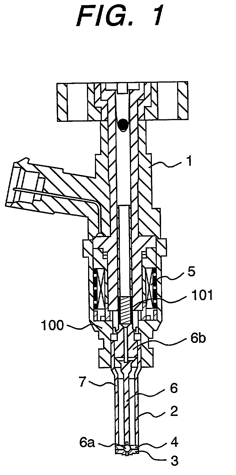
[0059]FIG. 1 is a longitudinal section of a fuel injector valve equipped with a nozzle body formed by drawing. The fuel injector 1 has an electromagnetic coil 5 and return spring 101, built in a housing 100, for driving a valve element 6. A housing 101 functions as part of a magnetic circuit when the electromagnetic coil 5 is excited. The nozzle body 2 formed by drawing is installed on the end of the housing 101. An orifice plate 3 for injecting fuel and a swirler 4 for providing the fuel with a swirling force are connected to the end of the nozzle body 2.

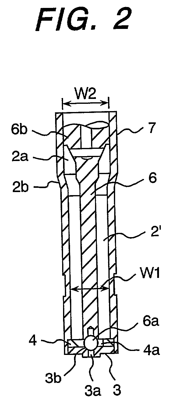
[0060]The valve element 6, which can be reciprocated along the axial direction as the electromagnetic coil 5 is energized, is built in the nozzle body 2. FIG. 2 is an enlarged view of a valve assembly 7 comprising the nozzle body 2, orifice plate 3, swirler 4, and valve element 6.

[0061]The...


PUM

PropertyMeasurementUnit
Anisotropyaaaaaaaaaa

Abstract

To manufacture a cylindrical member, such as the nozzle body of a fuel injector, in which a fluid passage is formed at high productivity and to improve the reliability.A cylindrical member, such as the nozzle body of a fuel injector, in which a fluid passage is formed is manufactured by drawing martenstic stainless steel. In addition, during the drawing process of martenstic stainless steel, an intermediate product is annealed and lug is removed after another drawing process, and then is subjected to drawing again to obtain a product.

Description

BACKGROUND OF THE INVENTION[0001]1. Field of the Invention[0002]The present invention relates to a fuel injector (injection valve) and a nozzle body thereof, and also to a method of manufacturing a cylindrical part equipped with a fluid passage, such as a nozzle body.[0003]2. Prior Art[0004]Since the nozzle body of a fuel injector has been required to have corrosion resistance and abrasion resistance, martenstic (martensite) stainless steel has been used as the material meeting the requirement.[0005]A conventional nozzle body made of martenstic stainless steel has been manufactured by cutting or forging.[0006]The Japanese Application Patent Laid-Open Publication No. Hei 5-164016 proposes to manufacture some parts constituting a fuel injector (a case supporting a valve assembly, and a part supporting a coil assembly) by drawing, but nozzle body is not included.[0007]Other cylindrical part than a fuel injector, in which a fluid passage is formed, has never been manufactured by drawing...

Claims


Application Information

Patent Timeline
IPC IPC(8): B21D22/21B21D22/28B21D51/16F02M51/06F02M61/12F02M61/16F16K31/06
CPCB21D22/21F02M51/0671F02M61/166
Inventor KOSHIZAKA, ATSUSHISEKINE, ATSUSHIKAWAHARA, KEIJIYOKOYAMA, MIZUHO
Owner HITACHI LTD
Learn More