
Apparatus for thermal swing adsorption and thermally-enhanced pressure swing adsorption

a technology of apparatus and gas, applied in the direction of electrochemical generators, sustainable manufacturing/processing, separation processes, etc., can solve the problems of adsorption separation technology, use of excess energy, bulky apparatus, etc., and achieve the effects of reducing time and/or larger volumes, rapid sorbent regeneration, and excellent device stability

Inactive Publication Date: 2005-12-13
BATTELLE MEMORIAL INST
View PDF42 Cites 102 Cited by
  • Summary
  • Abstract
  • Description
  • Claims
  • Application Information

AI Technical Summary

Benefits of technology

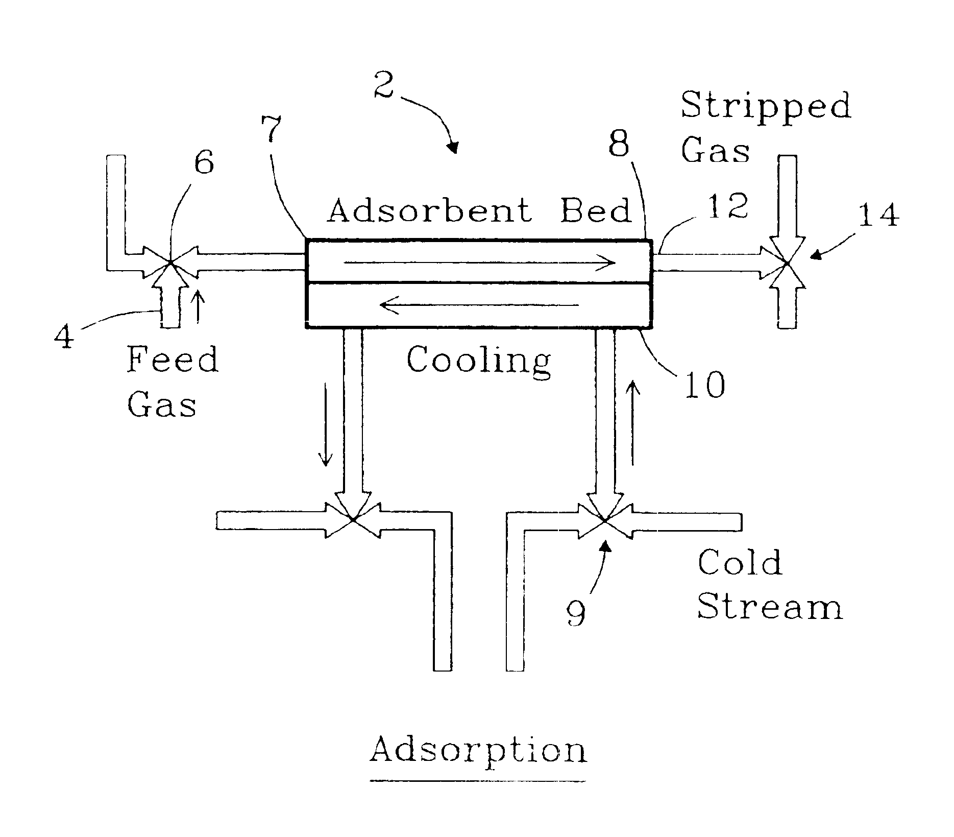
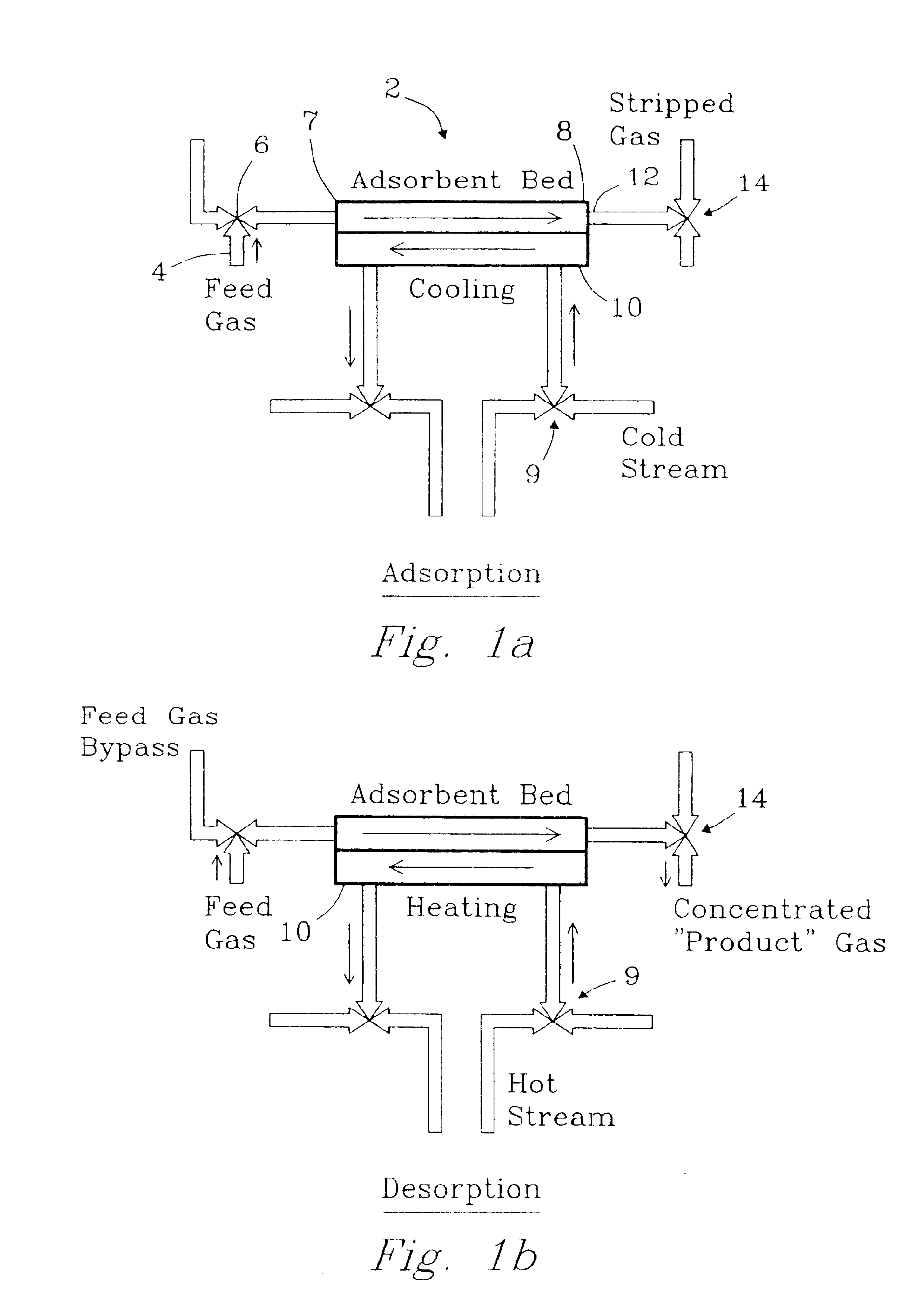
[0014]The invention also provides an apparatus in which adsorption / desorption cells are connected to improve overall energy efficiency. Each cell contains at least one adsorption mesochannel having an inlet and / or outlet. Typically, each cell contains multiple adsorption mesochannels that share a common header and common footer, and that are operated together. Preferably, each adsorption channel is in thermal contact with at least one heat exchanger. Each adsorption channel contains adsorption media. Typically, the apparatus also contains or is used in conjunction with a heat source and a heat sink. In some embodiments, the heat sink could be the non-adsorbed gas, which is passed through and removed from the apparatus. The apparatus contains heat transfer conduits between each cell and the heat source and heat sink and also contains heat transfer conduits between each cell and at least two other cells. In operation, the conduits carry a heat exchange fluid or can contain a thermally conductive material. The apparatus also contains valves that can control gas flow into the at least one adsorption channel. Cell volume is defined as the volume of the adsorption channel or channels that are operated together, including the volume of the heat exchange channel or channels, the volume between such channels, the volume of the outer walls of the cells, and the volume of inlet and outlet footers, when present.
[0015]The invention further provides a method of gas adsorption and desorption, comprising passing a gas into an adsorption layer where at least a portion of the gas is adsorbed onto adsorption media to form an adsorbed gas and selectively removing heat from the adsorption layer through a distance of 1 cm, preferably 2 mm, or less into a heat exchanger; and, subsequently, selectively heating the adsorption media through a distance of 1 cm, preferably 2 mm, or less from a heat exchanger, and desorbing gas. The gas directly contacts the adsorption media without first passing through a contactor material. For more rapid heat transfer (and thus faster cycling), the adsorption channel may contain heat transfer agents such as metal fins or pins, or graphite fibers.
[0022]Various embodiments of the invention can provide numerous advantages including one or more of the following: rapid cycling, rapid sorbent regeneration, reduced time and / or larger volumes of gas adsorbed as a function of sorbent mass required, excellent device stability, low cost, direct sorption into the sorption media without requiring diffusion through a contactor, preferential heating / cooling of the sorption media to a greater degree than other elements of the adsorber structure, configurations of sorption units with recuperative heat exchange thereby allowing energetically efficient temperature swing separations and / or more energetically-efficient, thermochemical compression.

Problems solved by technology

Despite their long-known use and importance, multiple problems remain with gas adsorption separation technologies.
These problems include: use of excess energy, bulky apparatus or low capacity, cost, and slow rate and / or low mass of gas separated.

Method used


Image

  • Apparatus for thermal swing adsorption and thermally-enhanced pressure swing adsorption
  • Apparatus for thermal swing adsorption and thermally-enhanced pressure swing adsorption
  • Apparatus for thermal swing adsorption and thermally-enhanced pressure swing adsorption

Examples


example 1

Adsorbent Mass Reduction for Rapid Thermal Cycling

[0102]As a practical test case, consider the adsorption and desorption of pure CO2 from zeolite 13× at near atmospheric pressure. A vendor-supplied zeolite 13× isobar at 760-mm Hg CO2 pressure shows the equilibrium CO2 capacity q varies nearly linearly with temperature T, over the range of −50° C. to 100° C., per the relationship q=24.9-0.115⁢T100=0.249-0.00115⁢T(1)

Here, the units of q are kg CO2 / kg zeolite and T is in degrees Celsius (C). The theoretical working capacity per cycle qw for adsorption at a low bed temperature Tl and desorption at a higher temperature Th under the isobaric conditions is therefore expressed as qw=0.00115⁢(Th-Tl)=0.00115⁢ ⁢Δ⁢ ⁢T=mdesCO2mads(2)

The working capacity qw is the maximum amount of gas desorbed at Th when the gas is adsorbed to equilibrium loading at Tl. Experimentally, the actual working capacity was determined from the known amount of zeolite in the adsorbent bed and the volume of CO2 desorbed,...

example 2

Adsorbent Mass Reduction for a Thermochemical Compression Scheme

[0106]Example 1 describes an isobaric process, but many adsorption processes are not isobaric. Consider, for example, an application in which the goal is to achieve CO2 compression thermochemically using a mesochannel adsorption system. Here, it is proposed to use a thermal swing adsorption process to capture (adsorb) CO2 at low temperature and low pressure (e.g., ˜6 mm Hg) and deliver (desorb) CO2 at higher temperature and pressure (e.g., 760 mm Hg) to a fuel-producing chemical reactor. Since adsorption, not desorption, is favored by higher partial pressures of the adsorbed gas species, it is necessary to operate the thermal swing over a sufficient temperature range to have a net production of gas in each thermochemical compression cycle.

[0107]For demonstration purposes, we consider adsorption at −50° C. and 6 mm Hg of CO2 and desorption at 100° C. and 760 mm Hg of CO2, to provide greater than 125-times compression. Th...

example 3

Rapid Thermal Swing Adsorption Cycles in Mesochannel Devices Demonstrated

[0109]FIG. 7 shows the rapid thermal-swing capability for an all-metal mesochannel adsorber in a series of 1-minute heating and cooling phases. (In separate tests, it was determined that the heat-exchange surface measured temperatures depicted in the figure are representative of the zeolite bed temperature to within 1 to 2° C.). As the heat-exchange fluid flow rate was increased from 20 mL / min to 80 mL / min, the maximum and minimum adsorber temperatures approached the hot (70° C.) and cold (5° C.) reservoir temperatures. A larger temperature differential between adsorption and desorption cycles increases the zeolite working capacity, and therefore, a higher adsorbent working capacity is expected as the water flow rate is increased. FIG. 7 also shows that the approach to the maximum (or minimum) temperatures is faster with increasing heat-exchange fluid flow rate. The heating curves were fit to exponential decay ...


PUM

PropertyMeasurementUnit
Temperatureaaaaaaaaaa
Fractionaaaaaaaaaa

Abstract

The present invention provides compact adsorption systems that are capable of rapid temperature swings and rapid cycling. Novel methods of thermal swing adsorption and thermally-enhanced pressure swing adsorption are also described. In some aspects of the invention, a gas is passed through the adsorbent thus allowing heat exchangers to be very close to all portions of the adsorbent and utilize less space. In another aspect, the adsorption media is selectively heated, thus reducing energy costs. Methods and systems for gas adsorption / desorption having improved energy efficiency with capability of short cycle times are also described. Advantages of the invention include the ability to use (typically) 30-100 times less adsorbent compared to conventional systems.

Description

RELATED APPLICATIONS[0001]This application is a divisional of Ser. No. 09 / 845,776, filed Apr. 30, 2001, now U.S. Pat. No. 6,630,012, which is incorporated herein by reference.[0002]This invention was made with Government support under contract DE-AC0676RLO 1830 awarded by the U.S. Department of Energy. The Government has certain rights in this invention.FIELD OF THE INVENTION[0003]This invention relates to apparatus and methods of gas adsorption.BACKGROUND OF THE INVENTION[0004]Separations of gases have long been important in gas purification processes such as used industrially in gas purification. Removal of carbon dioxide continues to be an important objective for purifying air for humans to live underwater and in space. Other important technologies that can utilize improvements for gas separation include: fuel cells, ammonia production, fertilizer manufacture, oil refining, synthetic fuels production, natural gas sweetening, oil recovery and steel welding.[0005]The adsorption cap...

Claims


Application Information

Patent Timeline
IPC IPC(8): B01D53/04B01D53/047C01B3/56H01M8/04H01M8/06
CPCB01D53/0407C01B3/56H01M8/04014H01M8/04223H01M8/0662B01D53/02B01D53/0446B01D53/0462B01D53/047B01D2253/108B01D2257/504B01D2257/80B01D2259/40088B01D2259/4575C01B2203/043C01B2203/0475C01B2203/066H01M8/0612Y02C10/08Y02E60/50Y02C20/40Y02P20/133Y02P20/50Y02P20/151Y02P20/10H01M8/026H01M8/0263H01M8/0267
Inventor WEGENG, ROBERT S.RASSAT, SCOT D.STENKAMP, VICTORIA S.TEGROTENHUIS, WARD E.MATSON, DEAN W.DROST, M. KEVINVISWANATHAN, VILAYANUR V.
Owner BATTELLE MEMORIAL INST
Learn More