
Meltblown die having a reduced size

a technology of meltblown dies and dies, which is applied in the direction of dough shaping, manufacturing tools, and melt spinning methods, etc., can solve the problems of large space required per meltblown die, and little has been done to change the physics of the standard meltblown dies

Active Publication Date: 2005-12-06
KIMBERLY CLARK GLOBAL SALES LLC
View PDF85 Cites 13 Cited by
  • Summary
  • Abstract
  • Description
  • Claims
  • Application Information

AI Technical Summary

Benefits of technology

"The present invention provides a meltblown die with a smaller width in the machine direction compared to conventional dies. The die has a die body, a die tip, a first air plate, and a second air plate. The overall width of the die is less than about 16 centimeters. In one embodiment, the die tip has a top side, a bottom side, a first side, and a second side, and the first air plate and second air plate are in contact with the die tip to form channels for the attenuating fluid to pass through. The distribution chamber has a non-linear shape to provide a sturdy mechanism for holding the die tip in place during use. The die body may also have a mounting plate for mounting the air plates and die tip. The technical effects of the invention include improved efficiency and stability during the meltblown process."

Problems solved by technology

Over the years, there have been improvements to the mechanical and air distribution systems of the meltblown dies, but little has been accomplished to change the physics of the standard meltblown dies.
One of the problems with the current meltblown dies is the large amount of space required per meltblown die.

Method used


Image

  • Meltblown die having a reduced size
  • Meltblown die having a reduced size
  • Meltblown die having a reduced size

Examples


Embodiment Construction

[0039]To obtain a better understanding of the present invention, attention is directed to FIG. 1, which generally shows a conventional meltblowing process of the prior art. Generally described, in a meltblowing process, a hopper 10 provides polymer to extruder 12 which is driven by motor 11 and heated to bring the polymer to the desired temperature and viscosity. The molten polymer is provided to die 14 which may also be heated by means of heater 16. The die is connected by conduits 13 to a source of attenuating fluid. At the exit 19 of die 14, fibers 18 are formed and collected on a forming belt 20 with the aid of an optional suction box 15 formed a web 22 which may be compacted or otherwise bonded by rolls 24 and 26. Belt 20 may be rotated by means of a driven roll which may be either 21 or 23, for example. In FIG. 1, the direction and arrow 30 show a direction perpendicular to the machine direction, which is referred to as the cross-machine direction.

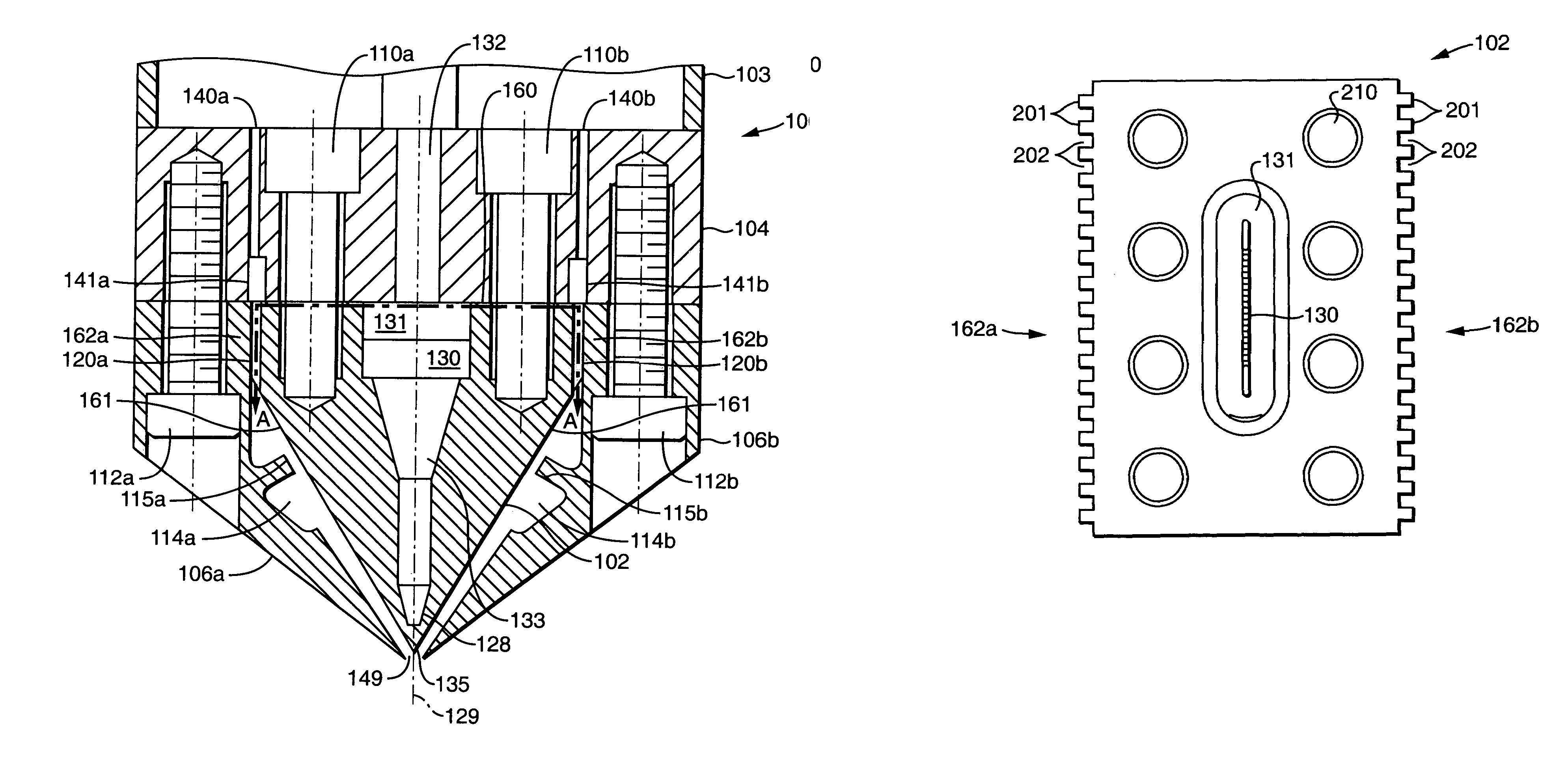
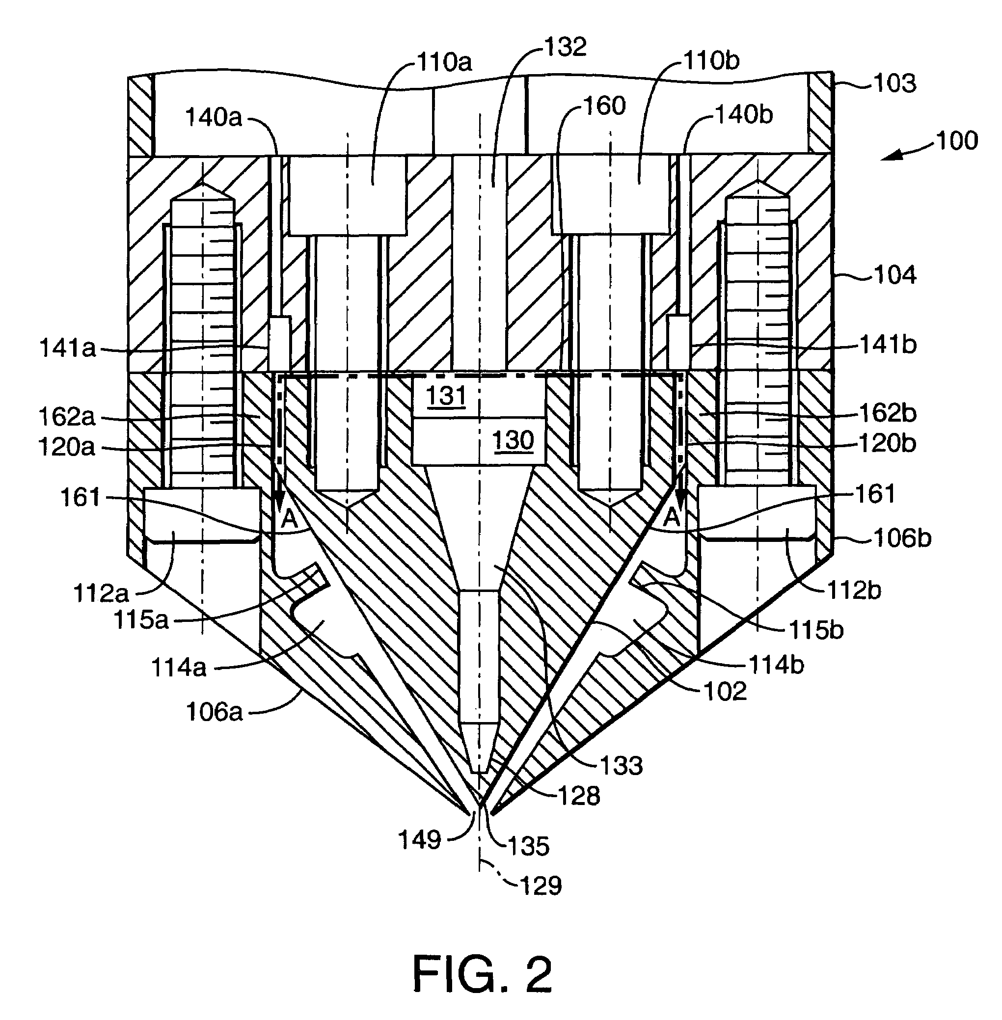
[0040]Turning to FIG. 2, this...


PUM

PropertyMeasurementUnit
widthaaaaaaaaaa
widthaaaaaaaaaa
angleaaaaaaaaaa

Abstract

The present invention provides a meltblown die which has a considerable smaller width in the machine direction of the meltblowing process compared to conventional and commercially used meltblown dies. The meltblown die of the present invention has a. a die body; b. a die tip mounted to the die body; c. a first air plate mounted to the die body; and d. a second air plate mounted to the die body. In addition, the small size of the meltblown die of the present invention provides advantages over conventional meltblown die, including improved air entrainment.

Description

FIELD OF THE INVENTION[0001]The present invention relates to a meltblown die assembly and the formation of fibers using the meltblown die assembly in a meltblowing process.BACKGROUND OF THE INVENTION[0002]The formation of fibers and nonwoven webs by meltblowing is well known in the art. See, by way of example, U.S. Pat. No. 3,016,599 to R. W. Perry, Jr.; U.S. Pat. No. 3,704,198 to J. S. Prentice; U.S. Pat. No. 3,755,527 to J. P. Keller et al.; U.S. Pat. No. 3,849,241 to R. R. Butin et al.; U.S. Pat. No. 3,978,185 to R. R. Butin et al.; U.S. Pat. No. 4,100,324 to R. A. Anderson et al.; U.S. Pat. No. 4,118,531 to E. R. Hauser; and U.S. Pat. No. 4,663,220 to T. J. Wisneski et al.[0003]Briefly, meltblowing is a process developed for the formation of fibers and nonwoven webs; the fibers are formed by extruding a molten thermoplastic polymeric material, or polymer, through a plurality of small holes. The resulting molten threads or filaments pass into converging high velocity gas streams,...

Claims


Application Information

Patent Timeline
Patent Type & Authority Patents(United States)
IPC IPC(8): B29C48/30B29C48/345D01D4/02D01D5/098D04H1/56
CPCD01D4/025D01D5/0985D04H1/565Y10S425/017D04H1/56
Inventor HAYNES, BRYAN DAVIDCOOK, MICHAEL CHARLES
Owner KIMBERLY CLARK GLOBAL SALES LLC
Learn More