
Enclosure and biometric data collection for fingerprint sensor device

a fingerprint sensor and data collection technology, applied in the field of protective enclosures, can solve the problems of biometric sensors, high-sensitivity biometric sensors, and many environmental hazards, and achieve the effects of reducing the risk of accidental death, and reducing the safety of users

Inactive Publication Date: 2005-11-29
APPLE INC
View PDF17 Cites 168 Cited by
  • Summary
  • Abstract
  • Description
  • Claims
  • Application Information

AI Technical Summary

Benefits of technology

The patent describes an enclosure assembly for a fingerprint sensor that has a movable access piece that can be used to expose the fingerprint sensor for enrollment. The assembly also includes an image quality indicator to ensure the collected biometric information is acceptable. Additionally, the patent describes a method for enrolling a composite image of an object using a fingerprint sensor by capturing images of the object in two different positions and constructing a representative image from the two images. The technical effects of this invention include improved protection and easy enrollment of fingerprint sensors in various devices.

Problems solved by technology

Furthermore, the computer hardware required for recording and comparing fingerprint data can be centralized and accessed through a telecommunications network, centralized databases, and processing hardware, with the result that costs may be amortized across many more transactions than would be the case for distributed processing.
There are, however, disadvantages to biometric identification and verification.
For instance, biometric sensors, which are highly sensitive, are exposed to a number of environmental hazards, such as impact and electrostatic discharge.
There are also problems associated with acquiring an accurate image of the fingerprint image.
When a fingerprint is positioned on the sensor that does not overlap the enrolled image, access will be denied due to finger placement error.

Method used


Image

  • Enclosure and biometric data collection for fingerprint sensor device
  • Enclosure and biometric data collection for fingerprint sensor device
  • Enclosure and biometric data collection for fingerprint sensor device

Examples


Embodiment Construction

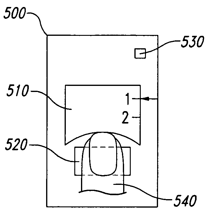
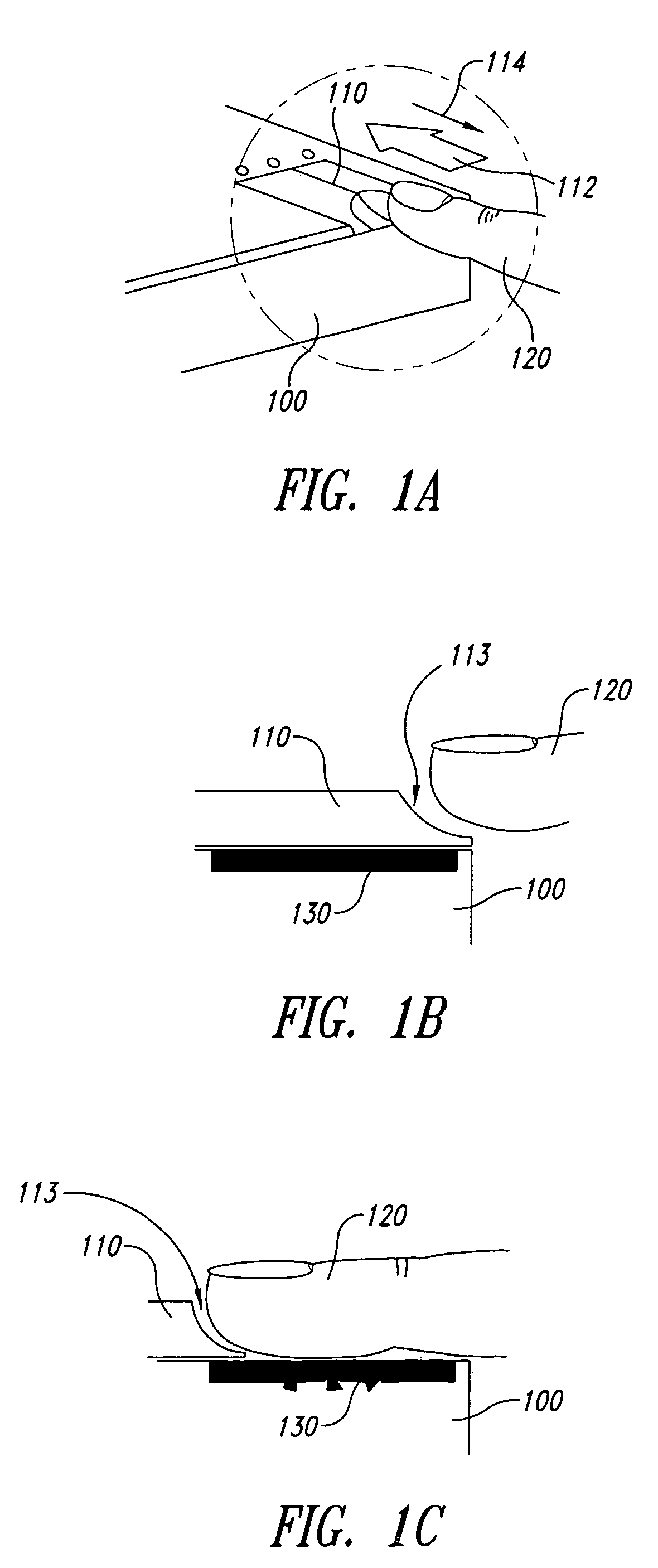
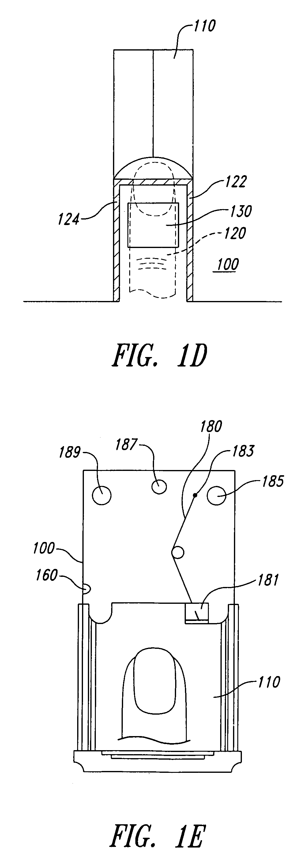
[0026]Provided is an apparatus and method for enclosing and operating a biometric sensor. An enclosure protects the sensor from harmful impacts, from electrostatic discharges (ESDs), and from other environmental hazards. In a preferred embodiment, the enclosure protects a biometric sensor used for sensing fingerprints, and the enclosure is configured to cause a fingerprint core to properly align with the sensor during an access procedure. In another embodiment, an apparatus is provided for indicating to the user when a fingerprint image of adequate quality is captured. The enclosure is also used during enrollment, and a method is provided for enrolling and reconstructing a fingerprint image that increases the likelihood of image overlap during an access procedure.

[0027]The preferred embodiment of the enclosure is shown in FIG. 1A. The enclosure 100 comprises and access piece 110 which is shown in the closed position. The access piece 110 is a sliding door, which is movable in the di...


PUM


Abstract

The enclosure assembly comprises a stationary member including at least two substantially parallel sidewalls, the sidewalls, the sidewalls partially defining a cavity in which the fingerprint sensor is disposed. An access piece, configured to move relative to the stationary member, has a surface area larger than the surface area of the fingerprint sensor and further includes a conductive portion electrically coupled to ground. A movement apparatus is preferably mechanically coupled to the stationary member and the moveable access piece. The movement apparatus is configured to maintain the moveable access piece in a position covering the fingerprint sensor and yet to allow motion of the moveable access piece relative to the stationary member so as to expose the fingerprint sensor. According to another embodiment, a method for enrolling a composite image of an object using a fingerprint sensor is provided. According to an embodiment, the method comprises the steps of receiving a finger disposed over a fingerprint sensor in a first stationary position; capturing a first image of a first portion of the finger with the fingerprint sensor; causing the finger to be repositioned over the fingerprint sensor in a second stationary position; capturing a second image of a second portion of the finger with the fingerprint sensor; and constructing a representative image of the finger from the first and second images.

Description

CROSS REFERENCE TO RELATED APPLICATIONS[0001]This application is a continuation of U.S. patent application Ser. No. 09 / 169,894, filed Oct. 12, 1998, now abandoned to which priority is claimed under U.S.C. Section 120. Furthermore, this application is related to U.S. Pat. No. 6,049,620, filed May 13, 1997, entitled “Capacitive Fingerprint Sensor Device With Adjustable Gain,” by Alexander G. Dickinson et al., and to U.S. patent application Ser. No. 08 / 971,455, filed Nov. 17, 1997, entitled “Automatic Adjustment Processing For Sensor Devices,” by inventors Lawrence O'Gorman et al. Each of the three above referenced patent and patent applications are incorporated herein by reference in their entirely.BACKGROUND OF INVENTION[0002]1. Field of the Invention[0003]The invention relates to enclosures and data collection for sensor devices, and more particularly to a protective enclosure, which also aligns an object placed on a biometric sensor.[0004]2. Background Information[0005]Biometric-or...

Claims


Application Information

Patent Timeline
Patent Type & Authority Patents(United States)
IPC IPC(8): A61B5/117G06K9/00
CPCA61B5/1172G06K9/0002G06K9/00026G06V40/1335G06V40/1306
Inventor O'GORMAN, LAWRENCEMILLER, WAYNE H.
Owner APPLE INC
Learn More