Circuit and system for extracting data
a data and circuit technology, applied in the direction of amplitude demodulation, instruments, generating/distributing signals, etc., can solve the problems of data or signal often having its eye pattern narrowed, waveform possibly affected by distortion, noise often entering the charging pump circuit, etc., to achieve the effect of much more accurate data extraction and higher response speed
- Summary
- Abstract
- Description
- Claims
- Application Information
AI Technical Summary
Benefits of technology
Problems solved by technology
Method used
Image
Examples
embodiment 1
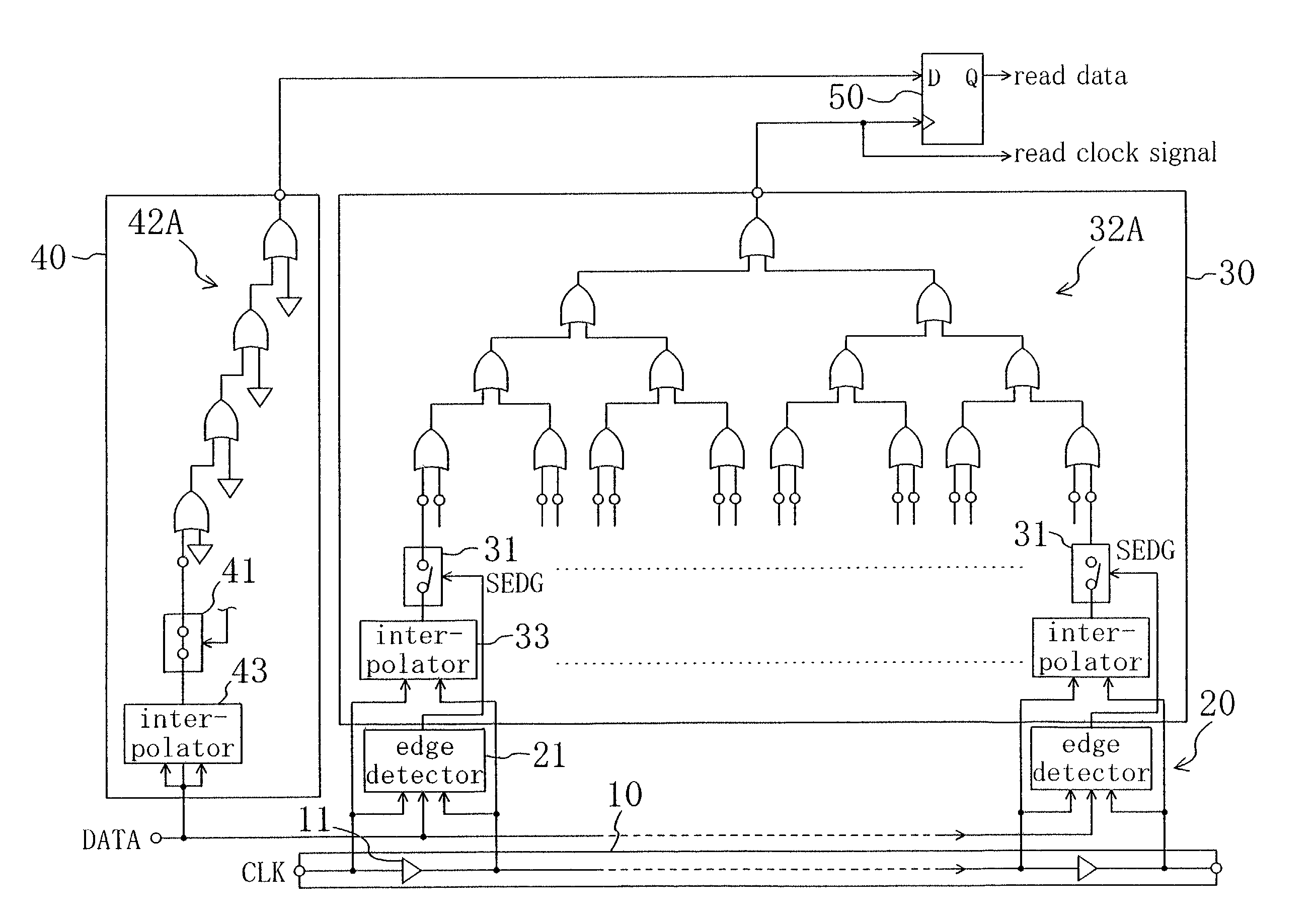
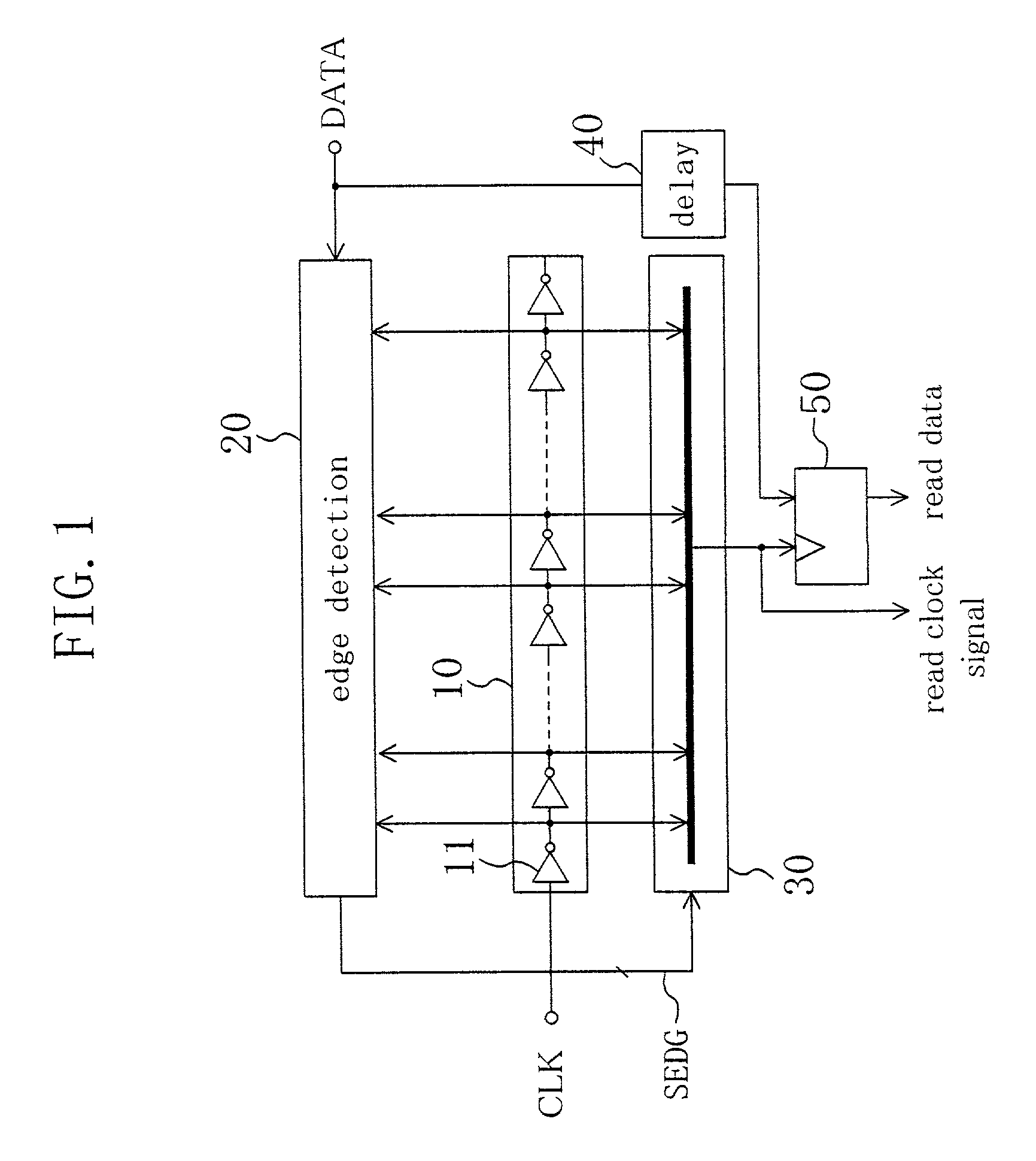
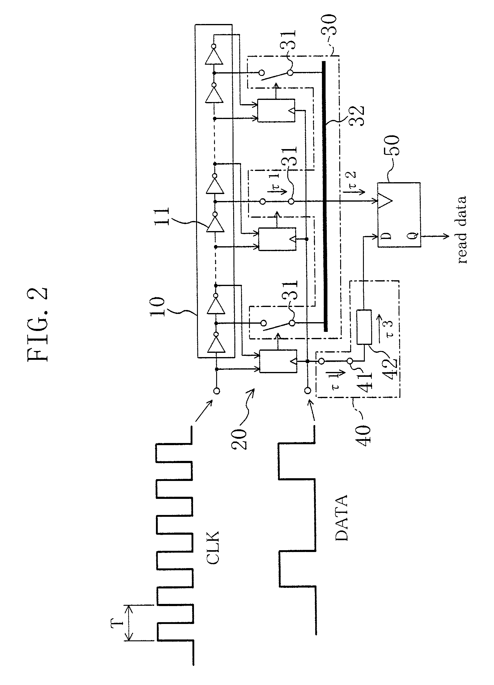
[0038]FIG. 1 illustrates a schematic configuration for a data extracting circuit according to a first embodiment of the present invention. As shown in FIG. 1, the circuit includes clock transfer section 10, edge detecting section 20, clock selecting section 30, delay circuit 40 and latch 50. The clock transfer section 10 includes multiple unit delay devices 11, which are connected in series together, and propagates an input clock signal CLK through the delay devices 11. Receiving the outputs of the respective delay devices 11 in the transfer section 10, the edge detecting section 20 locates an edge of the clock signal CLK and outputs an edge detection signal SEDG. The edge of the clock signal CLK should be located for one of the outputs of the delay devices 11. Responsive to the edge detection signal SEDG, the clock selecting section 30 selects the output of the delay device 11 for which the clock signal edge has been located. The delay circuit 40 delays an input data signal DATA fo...
embodiment 2
[0055]In the circuit configuration shown in FIG. 3 for the first embodiment, the OR gate tree 32A is provided for the clock selecting section 30 to considerably reduce the variation in delay between the outputs of the switches 31 and the output of the clock selecting section 30. However, the chip area occupied by the OR gate tree 32A will increase approximately in proportion to the square of the number of input signals, generally speaking. Accordingly, if a data extracting circuit with a higher time resolution should be implemented using the configuration shown in FIG. 3, then the chip area required will rise almost exponentially.
[0056]FIG. 6 is a circuit diagram illustrating a configuration for a data extracting circuit according to a second embodiment of the present invention. In the configuration shown in FIG. 6, the clock signal CLK, which has been selected by the clock transfer section 10, is not transferred through the OR gate tree 32A but through a selected clock transfer sec...
embodiment 3
[0065]By adding a known PLL circuit to the data extracting circuit of the first or second embodiment, a resulting extracting circuit can extract data from an input signal with any of various data rates covering a wider range and still realizes instantaneous response.
[0066]FIG. 10 illustrates a configuration for a data extracting circuit according to a third embodiment of the present invention. The data extracting circuit shown in FIG. 10 includes the extracting circuit 1 of the first or second embodiment and a known PLL circuit 2 in combination. In this configuration, the same data signal DATA is input to the extracting and PLL circuits 1 and 2, and the output clock signal of the PLL circuit 2 is presented as the input clock signal CLK to the extracting circuit 1.
[0067]The data extracting circuit of the first or second embodiment realizes instantaneous response to the data signal DATA presented thereto. To realize this fast response, however, the frequency of the clock signal CLK sh...
PUM
 Abstract
Description
Claims
Application Information
 - R&D
- Intellectual Property
- Life Sciences
- Materials
- Tech Scout
- Unparalleled Data Quality
- Higher Quality Content
- 60% Fewer Hallucinations
Browse by: Latest US Patents, China's latest patents, Technical Efficacy Thesaurus, Application Domain, Technology Topic, Popular Technical Reports.
© 2025 PatSnap. All rights reserved.Legal|Privacy policy|Modern Slavery Act Transparency Statement|Sitemap|About US| Contact US: help@patsnap.com


