
Method for moving contaminants from gases

a technology for moving contaminants and gases, applied in the direction of cleaning with liquids, bulk chemical production, separation processes, etc., can solve the problems of interfering with carbon dioxide applications of contaminated particles, and achieve the effect of effectively removing soluble contaminants and lowering contaminant levels

Inactive Publication Date: 2005-11-08
PRAXAIR TECH INC
View PDF18 Cites 33 Cited by
  • Summary
  • Abstract
  • Description
  • Claims
  • Application Information

AI Technical Summary

Benefits of technology

[0023]Emerging applications often require ultra-pure carbon dioxide with lower contaminant levels than demanded by previous processes. This invention recognizes that at high pressure, UHP carbon dioxide often includes dissolved contaminants. A change in condition can cause the dissolved contaminants to precipitate, forming an aerosol of gaseous carbon dioxide and suspended contaminant particles. The suspended contaminant particles can interfere with carbon dioxide applications. This invention generally relates to purifying carbon dioxide through the use of catalytic oxidation. This invention provides a method for effectively removing the soluble and non-soluble portions of NVOR such that suspended particles do not interfere with carbon dioxide applications.
[0027]The invention has several advantages. It provides a thermal catalytic oxidation (“catox”) means that can effectively reduce both vapor and liquid phase contaminant levels by orders of magnitude. Practicing the invention results in the removal of contaminants that precipitate from solution and form an aerosol of carbon dioxide gas and contaminant particles. A user of this invention can oxidize a sufficient portion of the contaminants so that the carbon dioxide can be used in an application without deposition of an unacceptable amount of contaminant particles in or onto the product.
[0029]The method of the invention can be conducted with near-critical, critical or supercritical carbon dioxide, thereby, eliminating the need for further compression downstream of the catalytic unit, and associated equipment such as pumps and / or compression units that can introduce contaminants into the carbon dioxide can be omitted. Oxidizing contaminants while the carbon dioxide is in a near-critical, critical, or supercritical state has advantages for breaking down the contaminants in the reactor since it will normally increase the fraction of the contaminant in the vapor phase.

Problems solved by technology

The suspended contaminant particles can interfere with carbon dioxide applications.

Method used


Image

  • Method for moving contaminants from gases
  • Method for moving contaminants from gases
  • Method for moving contaminants from gases

Examples


example 1

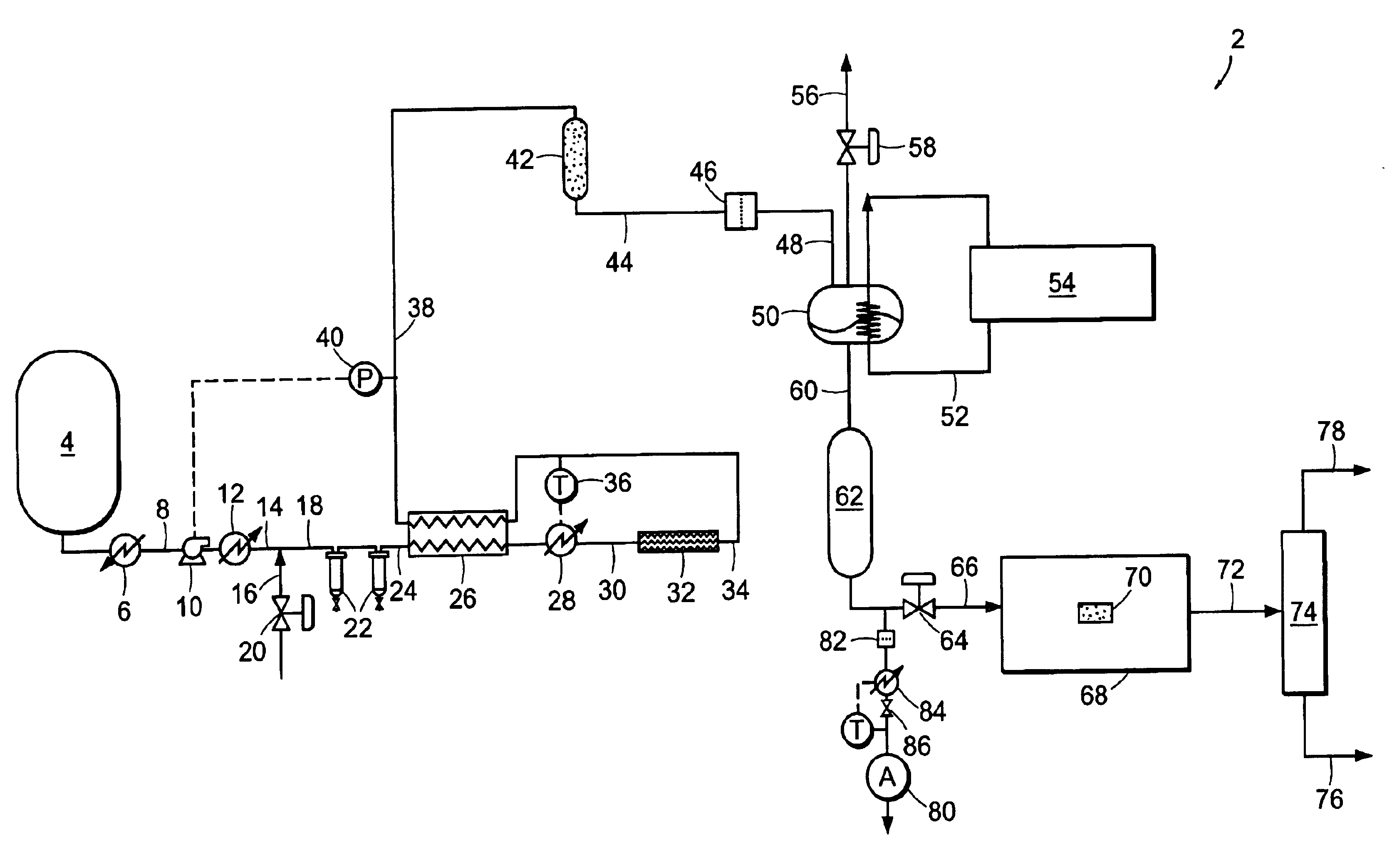
[0090]Carbon dioxide was purified in a system similar to system 2 illustrated in FIG. 1. Carbon dioxide was drawn from the vapor space of a carbon dioxide cylinder containing SFE grade carbon dioxide. The cylinder contained saturated liquid at ambient temperature, and a pressure of approximately 820 psia (˜5654 kPa). The vapor was then passed through coalescing filters operating at cylinder pressure. This stream was reduced in pressure and passed through a 0.003-micron electronics grade particle filter for removal of solid particles. Heat was applied upstream of the pressure reduction device to ensure that the carbon dioxide entering a downstream particle analyzer was approximately ambient temperature. FIG. 5 shows the particle counts as a function of the pressure to which the stream was reduced. At the highest pressure, the reduction in pressure is minor and so is the number of particles. This is consistent with the use of high efficiency coalescers. However, as the pressure is red...

example 2

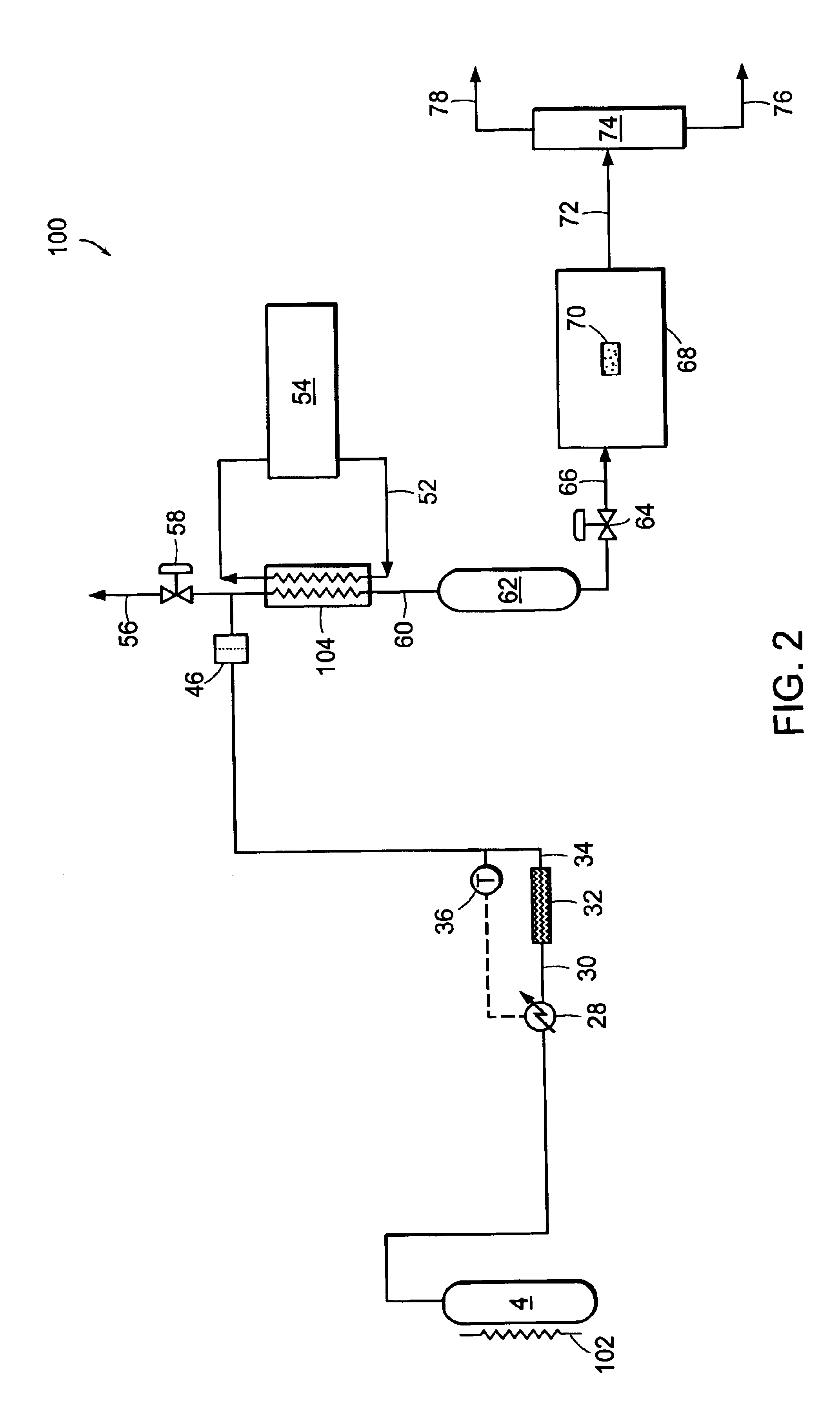
[0091]EIG carbon dioxide liquid at 300 psig (˜2068 kPa) was drawn from a bulk tank, vaporized, and passed through a thermal catalytic reactor. The catalyst reactor included three PRO*VOC 10 catalysts from Süd-Chemie Prototech, Inc. (Needham, Mass.). PRO*VOC 10 catalyst is a platinum-based metal on ceramic foam. The reactor was operated at various temperatures, from ambient (˜21.1° C.) to 315.6° C. The space velocity in all tests was 44,000 scfh / ft3 (44,000 standard cubic meters per hour per cubic meter of catalyst volume). Oxygen was added to the carbon dioxide upstream of the reactor to yield 600 ppm by volume oxygen in the mixture.

[0092]FIG. 6 shows the particle size distribution as a function of reactor temperature, where the particles were measured downstream of the reactor at ambient temperature and approximately the same pressure as the reactor. The number of particles measured when the reactor was at essentially room temperature is very high. However, the number of particles ...

example 3

[0096]EIG carbon dioxide was passed through a catalytic reactor, containing three PRO*VOC 10 catalysts (Pt-based metal on ceramic foam) as described in Example 2, again without coalescence prior to the reactor. The temperature of the reactor was 600° F. (315.5° C.), and excess oxygen (˜600 ppm by volume) was added to the stream. Under these conditions, particle counting at reactor pressure and ambient temperature showed essentially complete extinction of particles.

[0097]FIG. 8 shows a concurrent analysis of the stream in a low pressure particle analyzer operating at near ambient temperature and pressure, at two space velocities. The particle count in the vapor fed to the catalytic system is in excess of 107 per cubic foot (about 353 million particles per cubic meter) when measured at normal temperature and pressure. Downstream of the reactor it is reduced to about 600 and 100 particles per cubic foot (about 21,000 and 3,500 particles per cubic meter, respectively) when measured at N...


PUM

PropertyMeasurementUnit
diameteraaaaaaaaaa
temperaturesaaaaaaaaaa

Abstract

Carbon dioxide is purified through the use of catalytic oxidation. Carbon dioxide is exposed to at least one catalyst, oxidizing at least a portion of the nonvolatile organic residues to form purified carbon dioxide that is directed to an application. Carbon dioxide that is in a near-critical, critical, or supercritical phase can be exposed to the catalyst.

Description

RELATED APPLICATION(S)[0001]This application claims the benefit of U.S. Provisional Application No. 60 / 358,065, filed on Feb. 19, 2002. The entire teachings of the above application is incorporated herein by reference.BACKGROUND OF THE INVENTION[0002]Carbon dioxide supplied to food and beverage customers normally meets a purity specification known as Enhanced Ingredient Grade (EIG). Carbon dioxide of this purity is sufficient for use in food and beverages, and most plants can produce it.[0003]Some applications require carbon dioxide of higher purity than EIG. For example, supercritical fluid extraction and supercritical fluid chromatography require small amounts of higher purity carbon dioxide. Examples of the types of higher purity carbon dioxide include Supercritical Fluid Extraction (SFE) and Supercritical Fluid Chromatography (SFC) grades. These grades of carbon dioxide are generally supplied in cylinders.[0004]Additional applications requiring high purity and ultra-high purity ...

Claims


Application Information

Patent Timeline
Patent Type & Authority Patents(United States)
IPC IPC(8): B01D15/00C01B31/20C01B31/00C01B32/50C01B32/55F25J3/08
CPCC01B31/20F25J3/08F25J2205/40F25J2205/82F25J2205/84F25J2215/80F25J2220/82F25J2220/84F25J2235/80F25J2245/02F25J2260/80F25J2270/90F25J2290/60C01B32/50Y02P20/54B01D53/02C01B32/55
Inventor JOHNSON, MICHAEL CLINTONHEIM, CARL JOSEPHBILLINGHAM, JOHN FREDRIC
Owner PRAXAIR TECH INC
Learn More