Power converter with shunt resistor

a power converter and resistor technology, applied in the direction of resistor details, resistor housing/enclosement/embedding, one-port network, etc., can solve the problems of shunt resistor b>13/b> and the detection circuit b>18/b> cannot be made small in size, low resistance rate, cost reduction and miniaturization, etc. , to achieve the effect of suppressing heat generation, improving accuracy and low resistance ra

Inactive Publication Date: 2005-11-01
HITACHI LTD
View PDF51 Cites 6 Cited by
  • Summary
  • Abstract
  • Description
  • Claims
  • Application Information

AI Technical Summary

Benefits of technology

[0018]On the other hand, the shunt resistor 13 and the detection circuit 18 can be constituted by small and inexpensive electronic parts. However, the shunt resistor 13 and the detection circuit 18 are connected in series with a power line so as to detect a load current ranging from several amperes to several thousands of amperes. Thus, heat is generated. Although manganin material or the like having a low rate of resistance temperature change is used to improve the accuracy, the resistivity of the manganin material is several tens of times as high as that of copper material. Thus, the resistance value is required to be made a minimum (about 0.5–0.6 mΩ) in order to suppress heat generation. When the sheet-like resistive material 6 is made thick and short, the bottom area of the resistive material is reduced. As a result, the heat radiation resistance increases to cause temperature increase. Further, heat is generated also in the shunt resistance 8 and the main electrodes 7 for making the load current flow into the shunt resistance 8. Thus, the amount of heat generated in the shunt resistor as a whole is increased. Indeed such increase of the amount of heat generated in the shunt resistor as a whole can be avoided by increasing the size of the main electrodes 7 to thereby increase the heat radiation area and reduce the thermal resistance. But the shunt resistor 13 and the detection circuit 18 cannot be made small in size and low in cost. Thus, it is difficult to apply the shunt resistor 13 and the detection circuit 18 to a high-capacity power converter. Further, the load current does not flow into the shunt resistor 13 uniformly by electromagnetic induction caused by the layout of power wiring to the shunt resistor 13. Thus, there arises a problem that heat generation is concentrated or the detection accuracy deteriorates.
[0019]An object of the invention is to provide a power converter excellent in control characteristics, small in size and low in cost, by use of an accurate and compact shunt resistor whose thermal resistance is reduced so that the system for detecting a load current by the shunt resistor and a detection circuit can be applied to a high-capacity power converter, while the load current distribution in the shunt resistor is made uniform.
[0020]The foregoing object is attained by a power converter in which a load current is detected from the shunt resistor 13 constituted by three parts, that is, the shunt resistance 8 and two main electrodes 7. In the power converter, the shunt resistance 8 and the main electrodes 7 are formed out of one and the same sheet-like resistive plate 6. One side of the shunt resistor 13 is fixedly attached to the insulating layer 4. Sheet-like plates 9 are fixedly attached to side surfaces of the main electrodes 7 opposite to the side surfaces with which the main electrodes 7 are fixedly attached to the insulating layer 4. Each of the plates 9 is lower in volume electric resistivity than at least the sheet-like resistive plate 6 and thicker in thickness than the sheet-like resistive plate 6. Plate main electrodes 11 are provided on the plates 9, while plate detection electrodes 12 are provided on the plates 9 for detecting a voltage generated in the shunt resistance 8 and electrically connecting the detected voltage to another wiring. Accordingly, heat generated in the two main electrodes 7 formed out of the same sheet-like resistive plate 6 as the shunt resistance 8 can be reduced on a large scale. Further, since the detection electrodes are provided on the plates 9 having low volume electric resistivity, the power converter can be made smaller in size and higher in accuracy.
[0021]The foregoing object is attained by a power converter in which a load current is detected from the shunt resistor 13 constituted by three parts, that is, the shunt resistance 8 and two main electrodes 7. In the power converter, the shunt resistance 8 and the main electrodes 7 are formed out of one and the same sheet-like resistive plate 6. One side of the shunt resistor 13 is fixedly attached to the insulating layer 4. Sheet-like plates 9 are fixedly attached to the other surfaces of the main electrodes 7 respectively. Each of the plates 9 is lower in volume electric resistivity and higher in thermal conductivity than at least the sheet-like resistive plate 6 and thicker in thickness than the sheet-like resistive plate 6. Plate main electrodes 11 are provided on the plates 9, while plate detection electrodes 12 are provided on the plates 9 for detecting a voltage generated in the shunt resistance 8 and electrically connecting the detected voltage to another wiring. Accordingly, heat generated in the shunt resistance 8 can be thermally transmitted and thermally diffused by use of the plates 9. Thus, the thermal resistance of the shunt resistor 13 can be reduced.
[0022]The foregoing object is attained by a power converter in which a load current is detected from the shunt resistor 13 constituted by three parts, that is, the shunt resistance 8 and two main electrodes 7. In the power converter, the shunt resistance 8 and the main electrodes 7 are formed out of one and the same sheet-like resistive plate 6. One side of the shunt resistor 13 is fixedly attached to the insulating layer 4. Sheet-like plates 9 are fixedly attached to the other surfaces of the main electrodes 7 respectively. Each of the plates 9 is lower in volume electric resistivity and higher in thermal conductivity than at least the sheet-like resistive plate 6 and thicker in thickness than the sheet-like resistive plate 6. Plate main electrodes 11 are provided on the plates 9, while at least one constricted portion 23 for narrowing a current flow path is provided between each of said main electrodes 11 for the plate main electrodes 11 and the shunt resistance 8 so as to be located in the plates 9 and the main electrodes 7. Accordingly, the flow path of a load current in the respective plates 9 and the respective main electrodes 7 can be controlled. Thus, the current density of the load current flowing into the shunt resistance 8 can be made uniform.

Problems solved by technology

However, in the case of the hall element type current sensor 28, a comparatively expensive hall element and a large magnetic substance are required.
Accordingly, there is a problem in cost reduction and miniaturization.
But the shunt resistor 13 and the detection circuit 18 cannot be made small in size and low in cost.
Thus, there arises a problem that heat generation is concentrated or the detection accuracy deteriorates.

Method used


Image

  • Power converter with shunt resistor
  • Power converter with shunt resistor
  • Power converter with shunt resistor

Examples


second embodiment

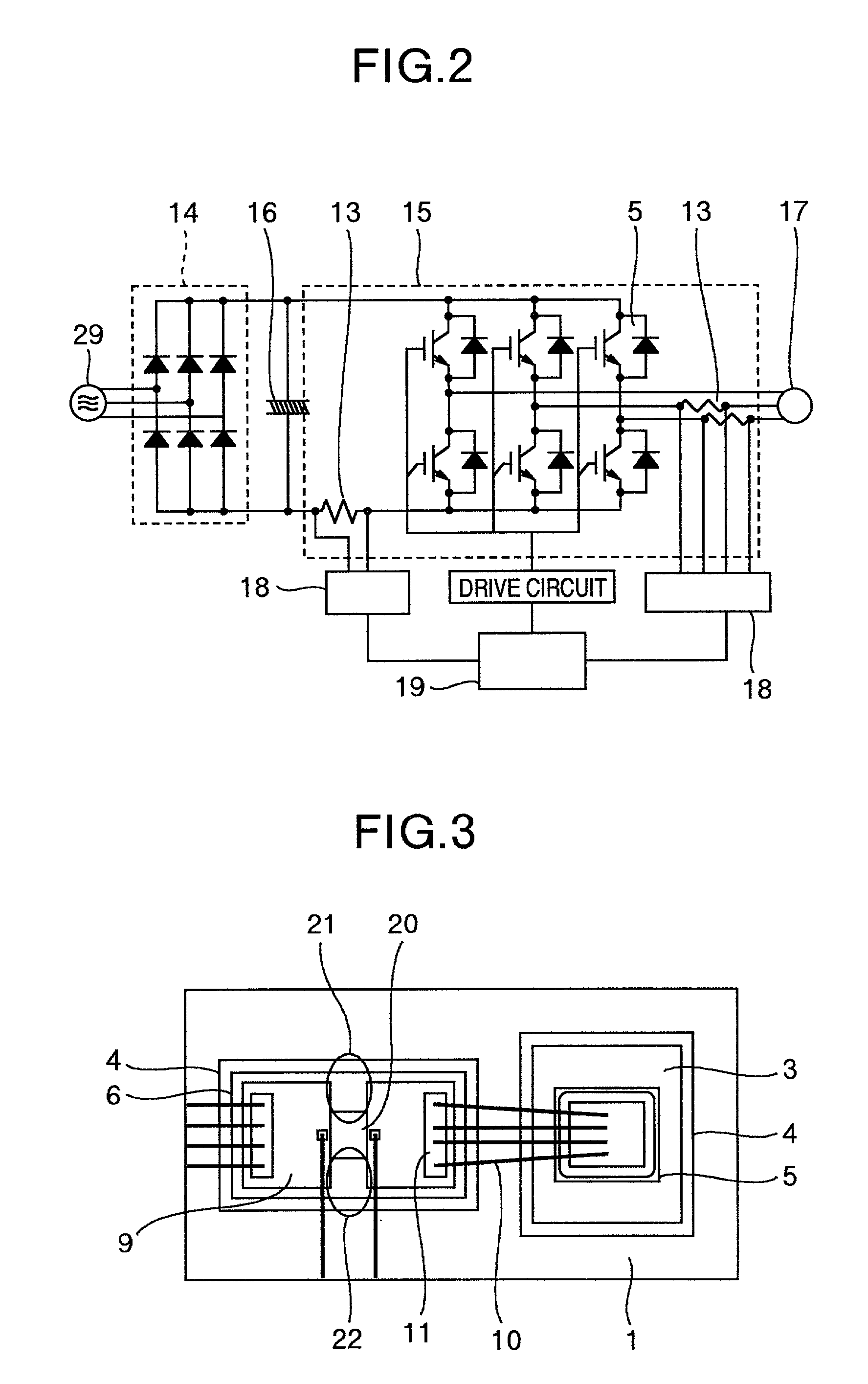
[0045]FIG. 3 shows an example of a shunt resistor according to the invention. This embodiment is different from the embodiment described in FIG. 1 in the following point. That is, at least one branch port 20 for branching a load current is provided in the shunt resistance 8 in FIG. 1, and a plurality of shunt resistances 8 (first and second shunt resistances 21 and 22 in FIG. 3) separated by the branch portion 20 are connected in parallel through the plates 9.

[0046]Thus, the distribution of the load current is made uniform by the plates 9 and the load current is branched equally to the respective shunt resistances 8 so that heat generation in the respective shunt resistances 8 is made uniform. In addition, the first and second shunt resistances 21 and 22 are spaced so that heat generated in the respective shunt resistances is made easy to extend transversely. Thus, heat resistance can be reduced so that the temperature increase in the first and second shunt resistances 21 and 22 can...

third embodiment

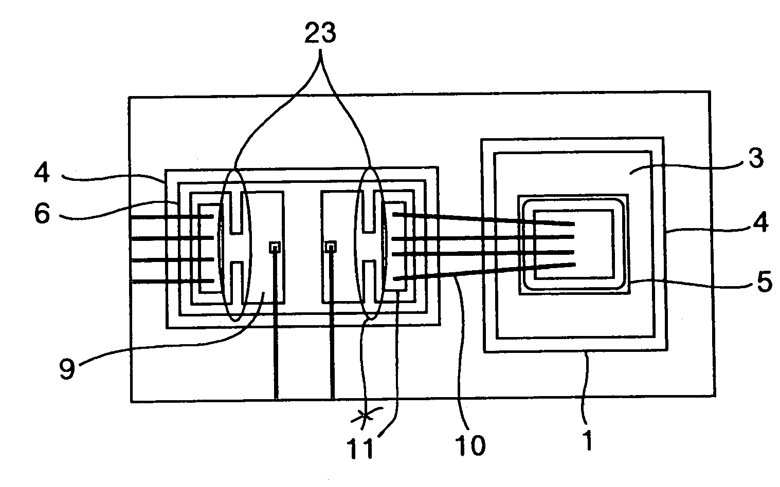
[0047]FIG. 4 shows an example of a shunt resistor according to the invention. This embodiment is different from the embodiment described in FIG. 1 in the following point. That is, at least one constricted portion 23 is provided between each of the plate main electrodes 11 provided on the plates 9 and the shunt resistance 8 in FIG. 1.

[0048]Unevenness of an electric current in the wiring pattern in the power module or in a terminal block and aluminum wire wiring appears due to electromagnetic induction caused by mutual inductance among main circuit wiring of the power converter, the wiring pattern in the power module, the terminal block and the aluminum wire wiring, and the shunt resistor. Unevenness of an electric current also appears in the wiring and the shunt resistor in the layout where the wiring is bent sharply near the shunt resistor. However, when the constricted portion 23 is provided on the plate main electrode 11 between the plate main electrode 11 and the shunt resistance...

fourth embodiment

[0052]FIG. 5 shows an example of a shunt resistor according to the invention. This embodiment is different from the embodiment described in FIG. 4 in the following point. That is, at least one of the center positions of the constricted portions 23 provided in the plates 9 in FIG. 4 is shifted from the same straight line.

[0053]Thus, unevenness of an electric current appearing in respective wires due to electromagnetic induction caused by mutual inductance among the wiring in the power module and the shunt resistor, or unevenness of an electric current appearing in the wiring and the shunt resistor in the layout where the connection wiring is bent sharply near the shunt resistor is rectified by use of the respective constricted portions provided in the respective plates 9. In this case, for example, the center of a first constricted portion 241 prepared in a first plate 91 is disposed on the longitudinal center line of the shunt resistance 8 while a second constricted portion 242 prep...


PUM


Abstract

A power converter includes a shunt resistor constituted by a shunt resistance and a plurality of main electrodes made of a sheet-like resistive material. In the shunt resistor, plates lower in volume electric resistivity than the resistive material, higher in thermal conductivity than the resistive material and thicker in thickness than the resistive material are fixedly attached by solder, to the side surfaces of the main electrodes opposite to the side surfaces with which the main electrodes are fixedly attached to an insulating layer. At least one plate main electrode for electrically connecting with main circuit wiring is provided in each of the plates. At least one constricted portion is formed between each of the plate main electrodes and the shunt resistance. Plate detection electrodes for detecting a voltage between the opposite ends of the shunt resistance is provided on the plates near the shunt resistance portion.

Description

BACKGROUND OF THE INVENTION[0001]The present invention relates to a power converter such as an inverter or a power storage, and particularly relates to a power converter of a pulse width modulation control system with an electric current detector using a shunt resistor.[0002]Inverters have been used widely for operating AC motors such as induction motors, and recently used also as controllers for power sources of carriages. Thus, the advantage of adjustable speed operation by using the inverters may be enjoyed sufficiently.[0003]For the control of an inverter, detection of a load current may be required. A hall element type current sensor 28 or a shunt resistor 13 with a detection circuit 18 has been conventionally adopted for the detection of the load current.[0004]The hall element type current sensor 28 is a current sensor in which a hall element is provided in a part of an annular magnetic substance, and an electric wire supplied with a load current is wound around or passed thro...

Claims


Application Information

Patent Timeline
Patent Type & Authority Patents(United States)
IPC IPC(8): H01C1/14H02M7/00H01C3/00H02M1/00
CPCH01C1/14H02M7/003
Inventor NAKATSU, KINYASASAKI, MASATAKASAITO, RYUICHIIBORI, SATOSHITAKASE, MASATO
Owner HITACHI LTD
Why Eureka
Try Eureka