
Fault tolerant automatic protection switching for distributed routers

a distributed router and fault-tolerant technology, applied in the field of data networking, can solve the problems of large amount of bandwidth, image and/or sound quality of the multimedia “stream” may be adversely affected, and real-time multimedia data also tends to be isochronous

Inactive Publication Date: 2005-10-18
EXTREME NETWORKS INC
View PDF3 Cites 82 Cited by
  • Summary
  • Abstract
  • Description
  • Claims
  • Application Information

AI Technical Summary

Benefits of technology

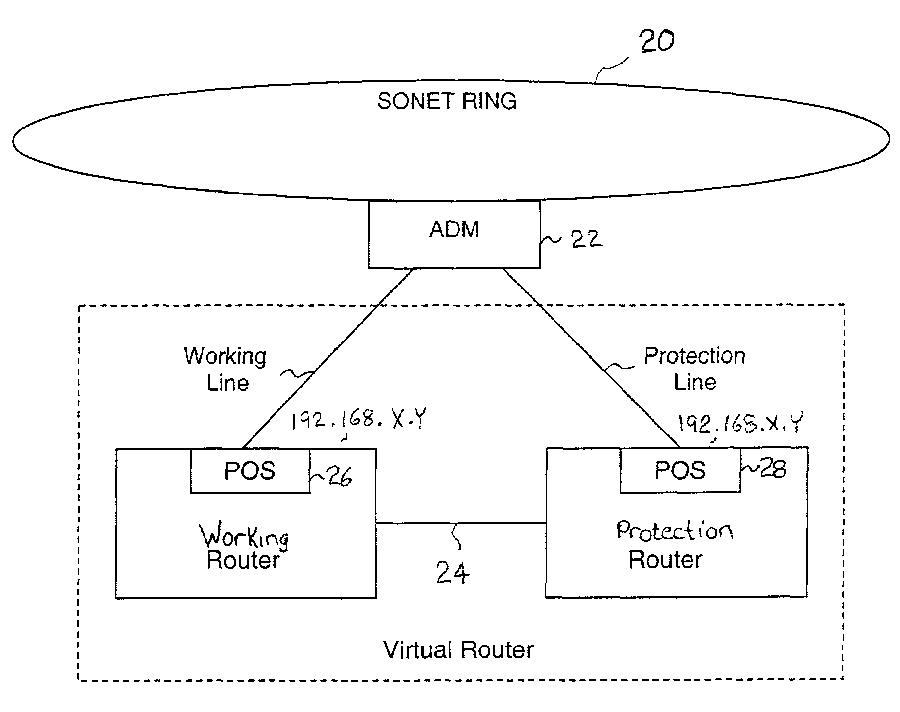
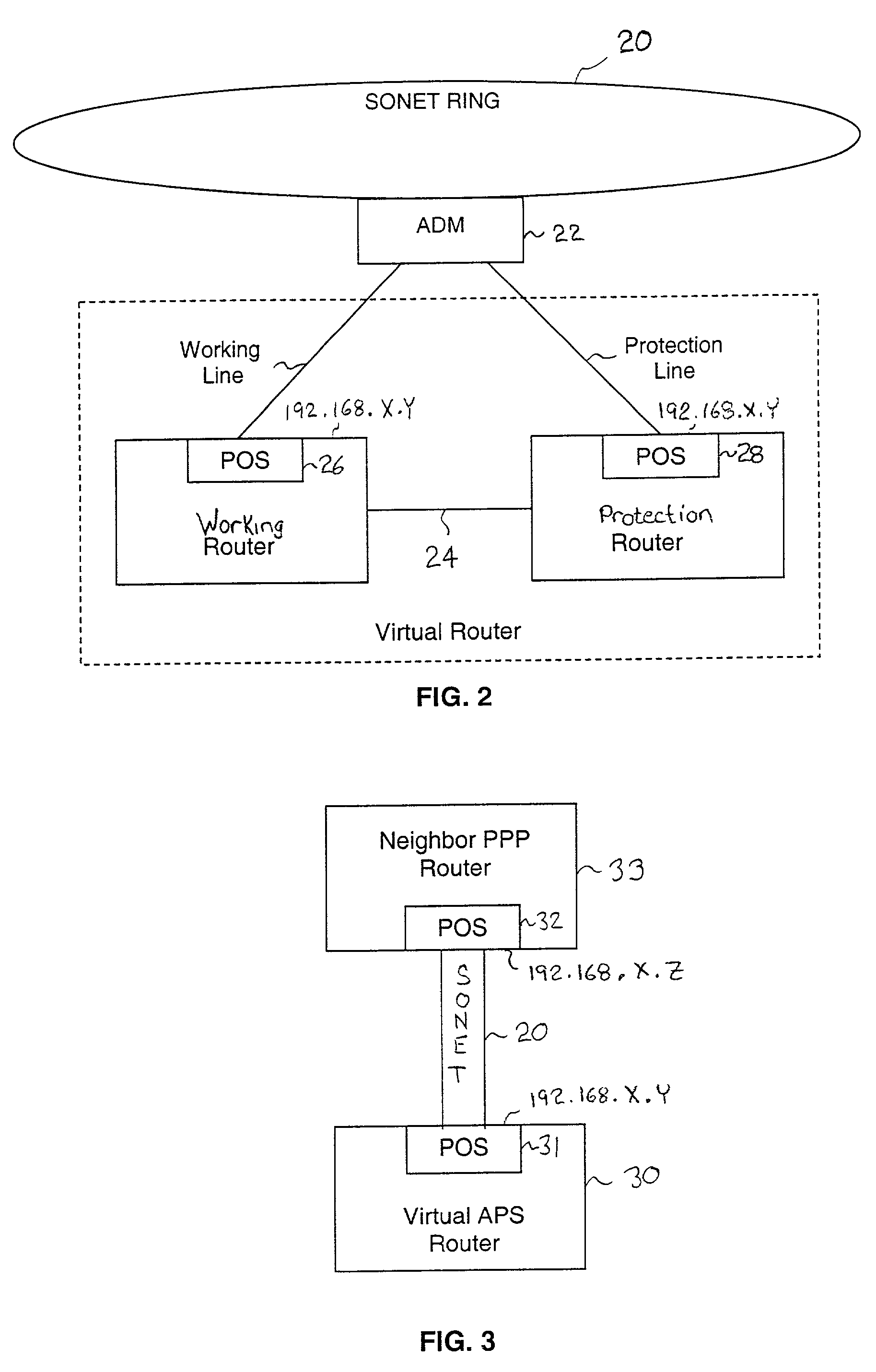
[0009]A fault tolerant switching architecture comprises a working router coupled to a SONET add-drop multiplexor (ADM) through a working line and a protection router coupled to the ADM through a redundant, protection line. Additionally, the working and protection routers are coupled to each other by way of a separate link, referred to as a side-band connection. The working router and protection router comprise a virtual router from the perspective of the neighboring router, which communicates with the virtual router over the SONET network using the Point-to-Point Protocol (PPP). The goal of the architecture is to provide fault tolerance in the event of either a line or router failure. According to one embodiment of the invention, the protection router transmits a heartbeat message to the working router over the side-band connection. If the protection router does not receive a response to the transmitted heartbeat message, the protection router initiates a line switch within the add-drop multiplexor. Once the line switch is complete, the protection router exchanges datagrams with the neighboring router, via the ADM and SONET ring to which the ADM is coupled. The protection router, in so doing, establishes a PPP connection between the protection router and the neighboring router device that is also coupled to the SONET ring. The PPP connection between the protection router and the neighboring router is established with the Link Control Protocol (LCP). The protection router includes a predetermined identifier value that identifies the originator of the request, in the LCP Identifier field of LCP request datagrams. According to the LCP specification, the neighboring router includes the LCP Identifier value received in a request datagram in the corresponding response datagram. The response datagram is transmitted over the SONET ring to the ADM. Because datagrams received by the ADM from the SONET link are transmitted over both the working and the protect lines, the working router will receive from the ADM the same response that was sent to the protection router. Thus, by examining the identifier field, and recognizing the identifier value as that assigned to the protection router, the working router is able to determine that the line switch to the protection router has occurred. This knowledge enables proper network operation in the case where the protection router loses contact with the working router due to a faulty side-band connection rather than a malfunctioning working router.

Problems solved by technology

In addition to requiring large amounts of bandwidth, real-time multimedia data also tends to be isochronous, in that it is to be received at a destination device at the same rate with which it was transmitted from the sending device.
If such real-time multimedia data is delayed during transmission between the source device and the destination device, the resulting image and / or sound quality of the multimedia “stream” may be adversely affected.
Such rerouting of data due to unexpected network outages may add significant delay to the total data transmission time.
One cause for unexpected network outages and associated data transmission delays may be attributed to excavation accidents where one or more network segments are severed.
Conventional copper networks, for example, tend to not be very resilient and are quite susceptible to such accidental severing or “backhoe fade.”
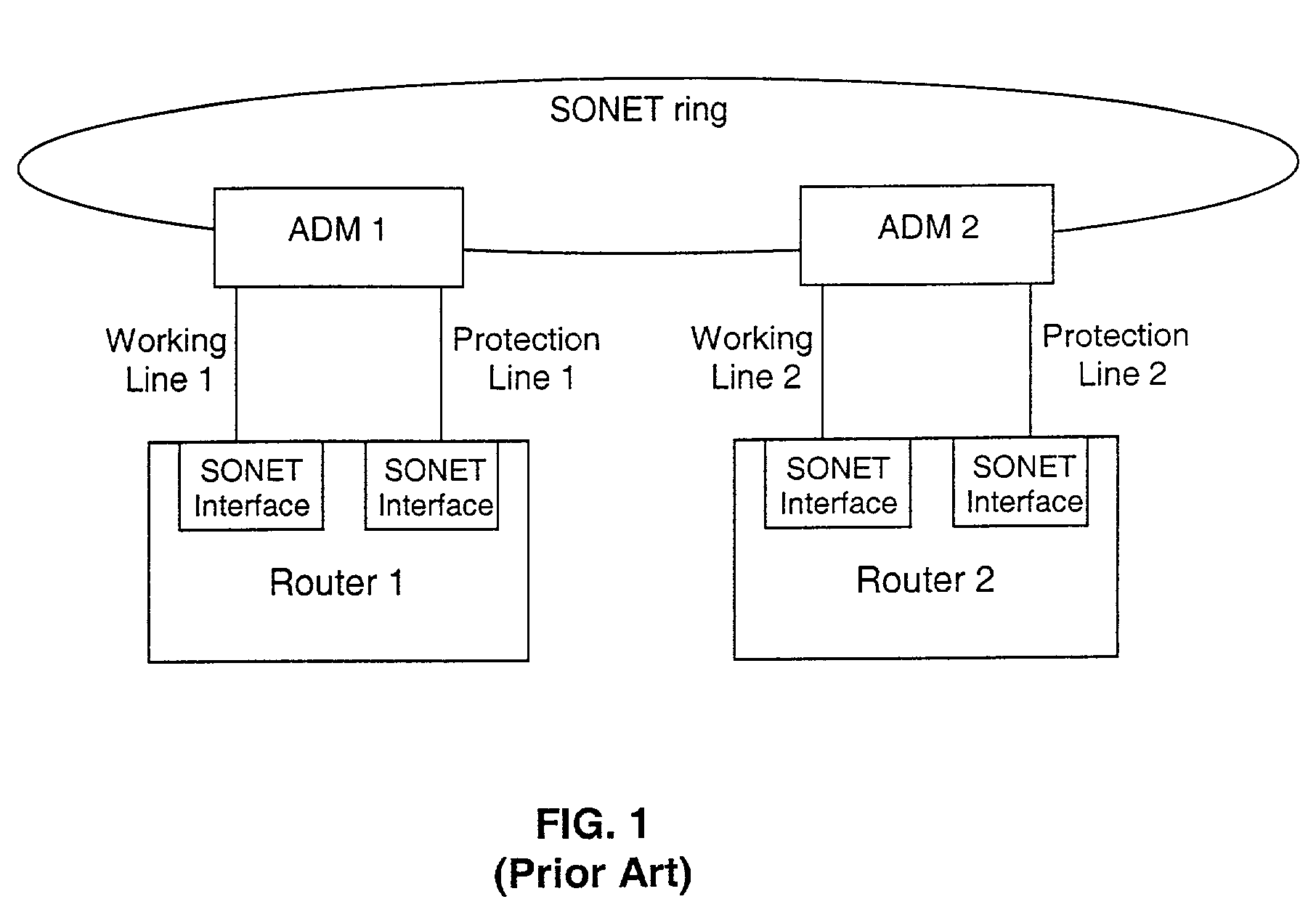
Neither implementation, however, protects against interruptions in network communication due to an entire router failure.

Method used


Image

  • Fault tolerant automatic protection switching for distributed routers
  • Fault tolerant automatic protection switching for distributed routers
  • Fault tolerant automatic protection switching for distributed routers

Examples


Embodiment Construction

[0018]In the following description, for purposes of explanation, numerous specific details are set forth in order to provide a thorough understanding of the invention. It will be apparent, however, to one skilled in the art that the invention can be practiced without these specific details. In other instances, structures and devices are shown in block diagram form in order to avoid obscuring the invention.

[0019]Reference in the specification to “one embodiment” or “an embodiment” means that a particular feature, structure, or characteristic described in connection with the embodiment is included in at least one embodiment of the invention. The appearances of the phrase “in one embodiment” in various places in the specification are not necessarily all referring to the same embodiment.

[0020]A fault tolerant switching architecture is described herein. More specifically, a novel two-router linear 1+1 APS architecture including both a working and a protection router is described herein. ...


PUM


Abstract

A working router is coupled to a SONET add-drop multiplexor (ADM) through a working line and a protection router is coupled to the ADM through a protection line. The routers are coupled to each other by a separate side-band connection and comprise a virtual router from the perspective of the neighboring router, which communicates with the virtual router over the SONET network using the Point-to-Point Protocol (PPP). The protection router transmits a heartbeat message to the working router over the side-band connection. If the protection router does not receive a response thereto, it initiates a line switch within the add-drop multiplexor. Once the line switch is complete, the protection router exchanges datagrams with the neighboring router, via the ADM and SONET ring to which the ADM is coupled. The protection router establishes a PPP connection between itself and the neighboring router device coupled to the SONET ring, utilizing the Link Control Protocol (LCP). The protection router includes a predetermined identifier value that identifies the originator of the request, in the LCP Identifier field of LCP request datagrams. The neighboring router includes the Identifier value received in a request datagram in the corresponding response datagram transmitted over the SONET ring to the ADM. Because datagrams received by the ADM from the SONET link are transmitted over both the working and the protect lines, the working router receives the same response as the protection router. Thus, by examining the identifier field, and recognizing the identifier value as that assigned to the protection router, the working router determines that the line switch to the protection router has occurred.

Description

FIELD OF THE INVENTION[0001]The invention relates generally to data networking. More specifically, the invention relates to fault tolerant switching within a data network.BACKGROUND OF THE INVENTION[0002]As the Internet continues to grow exponentially, the bandwidth requirements of the associated networks comprising the Internet similarly continue to grow. The transmission of large quantities of multimedia data, for example, including both audio and video data, has contributed to what has become a seemingly universal demand for increased network bandwidth. In addition to requiring large amounts of bandwidth, real-time multimedia data also tends to be isochronous, in that it is to be received at a destination device at the same rate with which it was transmitted from the sending device. If such real-time multimedia data is delayed during transmission between the source device and the destination device, the resulting image and / or sound quality of the multimedia “stream” may be advers...

Claims


Application Information

Patent Timeline
IPC IPC(8): H04J3/14H04J1/16H04J1/00H04J3/08H04L12/56H04Q11/04
CPCH04J3/08H04J3/14H04L45/22H04L45/28H04L45/58H04L45/586H04J2203/006H04J2203/0083
Inventor ALEXANDER, CEDELL A.GROSSER, DONALD B.
Owner EXTREME NETWORKS INC
Learn More