
System and method for suppressing noise in a phase-locked loop circuit

a phase-locked loop and loop circuit technology, applied in the direction of pulse automatic control, pulse technique, counting chain pulse counters, etc., can solve the problems of reducing the loop bandwidth to this value, affecting the lock time and phase noise in the pll, and the loop bandwidth not only affects channel spacing, so as to achieve the effect of suppressing nois

Inactive Publication Date: 2005-10-04
GCT SEMICONDUCTOR INC
View PDF9 Cites 29 Cited by
  • Summary
  • Abstract
  • Description
  • Claims
  • Application Information

AI Technical Summary

Benefits of technology

This approach effectively suppresses noise, enhancing signal quality and reducing lock time while maintaining flexibility in loop bandwidth settings, improving the overall performance of PLL circuits.

Problems solved by technology

Reducing the loop bandwidth to this value, however, produces a number of drawbacks.
For example, loop bandwidth not only affects channel spacing, it also affects the lock time and amount of phase noise in a PLL.
Therefore, reducing the loop bandwidth to a value smaller than the comparison frequency by a factor of ten will produce a commensurate increase in phase noise and lock time, which has found to be undesirable for many applications.
Another drawback of the aforementioned PLL relates to a second type of noise.
This noise appears in the form of spurious signals generated from mismatches that occur, for example, from the charge pump and the phase and frequency detector.
These mismatches generate spurious signals which propagate throughout the host system to degrade performance and therefore, like phase noise, are also considered to be undesirable.
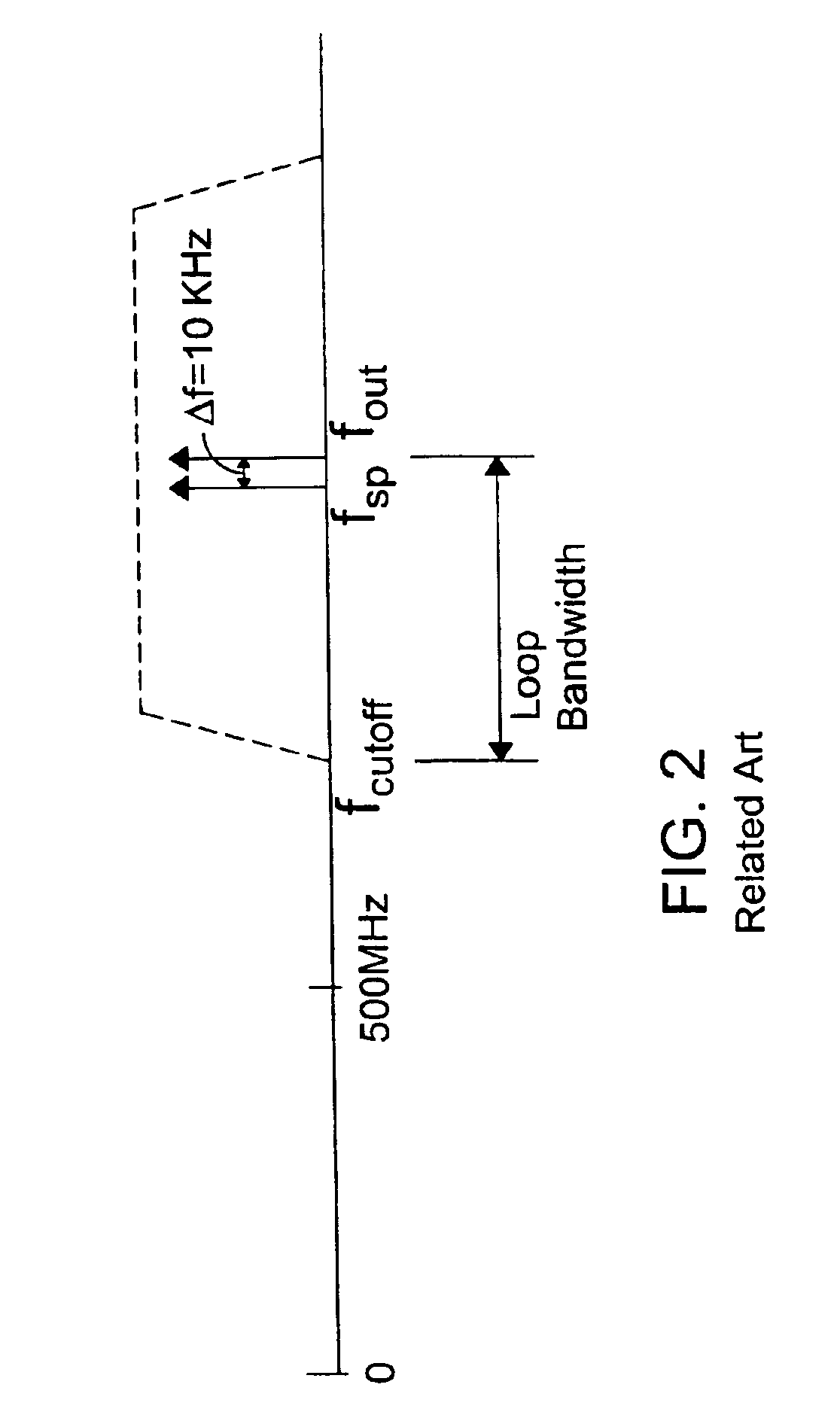
In fact, the spurious signals are so close to the output frequency (Δf is very small) that they lie within the loop bandwidth of the circuit and therefore cannot be removed by the loop filter.
These unsuppressed spurious signals further contribute to the degradation of signal quality and performance of the host system.

Method used


Image

  • System and method for suppressing noise in a phase-locked loop circuit
  • System and method for suppressing noise in a phase-locked loop circuit
  • System and method for suppressing noise in a phase-locked loop circuit

Examples


example

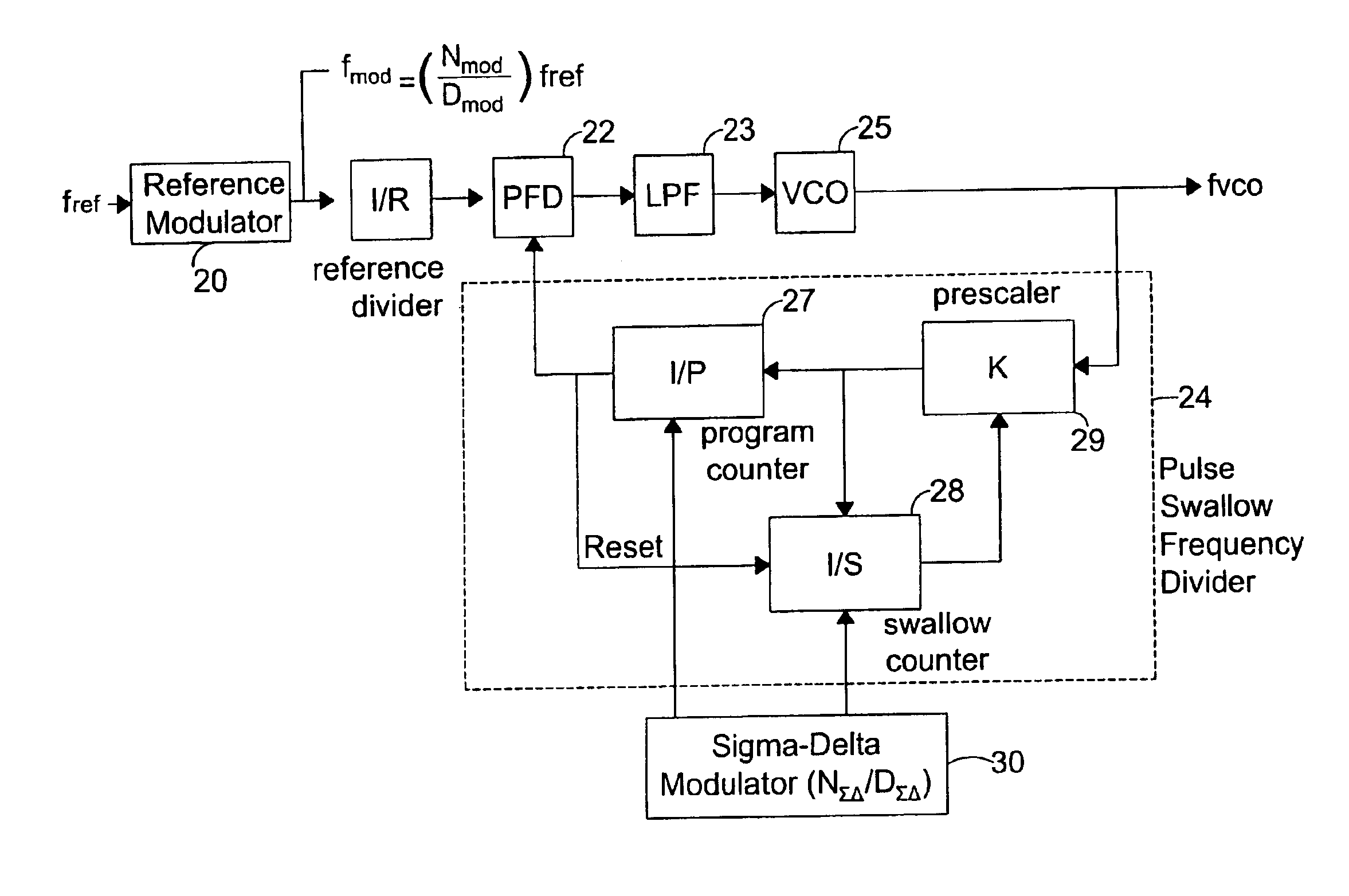
[0077]Table 2 shows exemplary values that may be used in accordance with the present invention. To achieve an acceptable level of spur reduction, the NΣ⁢ ⁢ΔDΣ⁢ ⁢Δ

ratio is selected to be large to shift spurious signals outside the cutoff frequency. Also, the reference frequency fref is modulated by an NmodDmod

ratio which ensures that the harmonics of fmod is not close to the harmonics of the original reference frequency fref.

[0078]

TABLE 2Nearest NFvco / for Fvco / FrefFvcoFrefFrefRKPSNDN / DNmodDmod46905.2919.6846.0005114112119680.00050818947924.9719.6847.0005114113119680.00050818948944.6519.6848.0005114120119680.00050818949964.3819.6849.0005114121119680.00050818950984.0119.6850.0005114122119680.000508189511003.719.6851.0005114123119680.000508189521023.419.6852.0005114130119680.000508189531043.119.6853.0005114131119680.000508189541062.719.6854.0005114132119680.000508189551082.119.6855.0005114133119680.000508189561102.119.6856.0005114140119680.000508189571121.819.6857.0005114141119680.00050...


PUM


Abstract

A system and method for improving the signal-to-noise ratio of a frequency generator suppresses phase noise and noise generated from mismatches in the internal generator circuits. This is accomplished using a modulation scheme which shifts spurious noise signals outside the loop bandwidth of the generator. When shifted in this manner, the noise signals maybe removed entirely or to any desired degree using, for example, a filter located along the signal path of the generator. In one embodiment, a Sigma-Delta modulator controls the value of a pulse-swallow frequency divider situated along a feedback path of a phase-locked loop to achieve a desired level of noise suppression. In another embodiment, a reference signal input into a phase-locked loop is modulated to effect noise suppression. In another embodiment, the foregoing forms of modulation are combined to accomplish the desired frequency shift. Through these modulation techniques, the signal-to-noise ratio of the frequency generator may be substantially improved while simultaneously achieving faster lock times.

Description

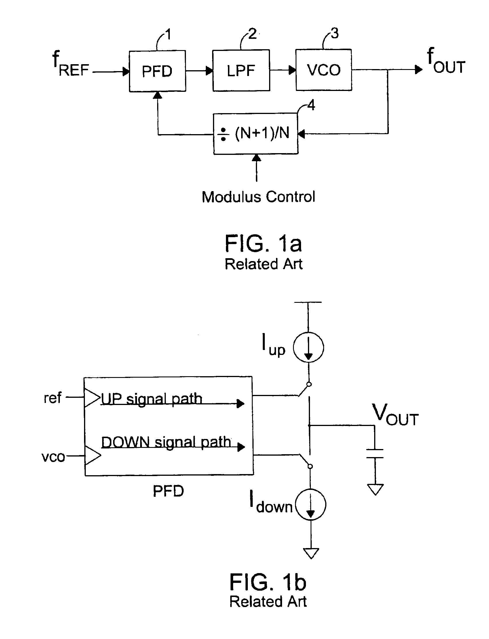
[0001]This application claims benefit to U.S. Provisional Patent Application 60 / 421,060, filed on Oct. 25, 2002, the entire contents of which are incorporated herein by reference.BACKGROUND OF THE INVENTION[0002]1. Field of the Invention[0003]This invention relates to generating frequency signals in a signal processing system.[0004]2. Description of the Related Art[0005]Phase-Locked Loop (PLL) circuits have been used in many wireline and wireless applications for generating carrier frequencies and timing reference signals.[0006]FIG. 1(a) shows a PLL which is commonly used in a communications transceiver. This circuit includes a phase and frequency detector 1, a loop filter 2, and a voltage-controlled oscillator 3 which outputs a signal fout at a desired frequency. A feedback loop connecting the oscillator to an input of the phase and frequency detector includes a divider 4 which divides the output of the oscillator by a value of (N+1) / N. A modulus control circuit outputs a signal to...

Claims


Application Information

Patent Timeline
Patent Type & Authority Patents(United States)
IPC IPC(8): H03L7/197H03L7/16
CPCH03L7/1978H03L7/06H03L7/085
Inventor AHN, YOUNGHOSONG, EUNSEOKKOO, YIDOLEE, JEONG-WOOPARK, JOONBAELEE, KYEONGHO
Owner GCT SEMICONDUCTOR INC
Learn More