
RISC processor supporting one or more uninterruptible co-processors

a co-processor and core processor technology, applied in the field of core processors for decoding systems, can solve the problem that issued instructions cannot be cancelled or re-issued

Active Publication Date: 2005-09-13
QUALCOMM INC
View PDF3 Cites 49 Cited by
  • Summary
  • Abstract
  • Description
  • Claims
  • Application Information

AI Technical Summary

Benefits of technology

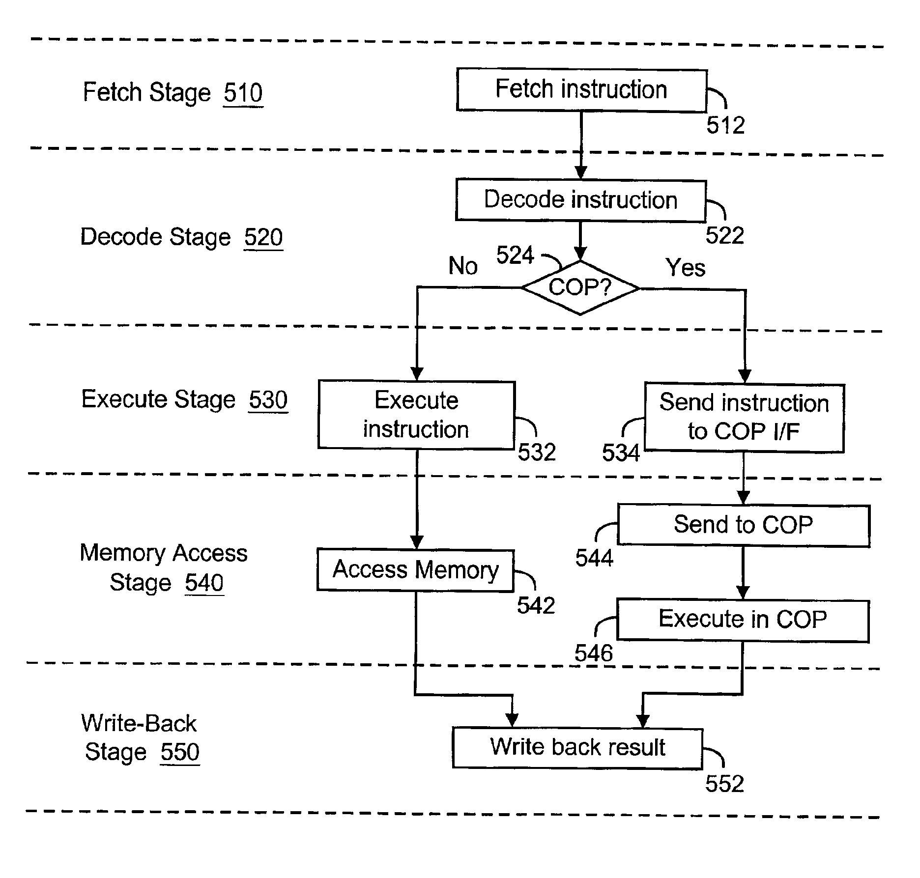
[0006]One aspect of the present invention is directed to a method of processing instructions in a computer system comprising a processor and a co-processor communicatively coupled to the processor. Pursuant to the method, instructions are processed in the processor in an instruction pipeline. In the instruction pipeline, instructions are processed sequentially by an instruction fetch stage, an instruction decode stage, an instruction execute stage, a memory access stage and a result write-back stage. If a co-processor instruction is received by the processor, the co-processor instruction is held in the core processor until the co-processor instruction reaches the exception raising stage, at which time the co-processor instruction is transmitted to the co-processor.
[0007]Another embodiment of the present invention is directed to a computer system having a processor and a co-processor. The processor processes instructions in an instruction pipeline. In the instruction pipeline, instructions are processed sequentially by an instruction fetch stage, an instruction decode stage, an instruction execute stage, a memory access stage and a result write-back stage. The co-processor is communicatively coupled to the processor and performs processing tasks in response to co-processor instructions provided by the processor. When the processor processes a co-processor instruction, the processor holds the co-processor instruction until the co-processor instruction reaches the exception raising stage, at which time the processor transmits the co-processor instruction to the co-processor.
[0008]Another embodiment of the present invention is directed to a computer system having a processor and a co-processor. The processor processes instructions in an instruction pipeline. In the instruction pipeline, instructions are processed sequentially by an instruction fetch stage, an instruction decode stage, an instruction execute stage, a memory access stage and a result write-back stage. The co-processor is communicatively coupled to the processor and performs processing tasks in response to co-processor instructions provided by the processor. When the processor processes a co-processor instruction, it dispatches the instruction to the co-processor at the decode stage or the execution stage, the co-processor can start executing the initial part of the co-processor instruction that does not change the state of the co-processor, the rest of execution cannot be started until the co-processor instruction reaches the exception raising stage.

Problems solved by technology

This condition can cause problems in co-processors in which an issued instruction cannot be cancelled or re-issued.

Method used


Image

  • RISC processor supporting one or more uninterruptible co-processors
  • RISC processor supporting one or more uninterruptible co-processors
  • RISC processor supporting one or more uninterruptible co-processors

Examples


Embodiment Construction

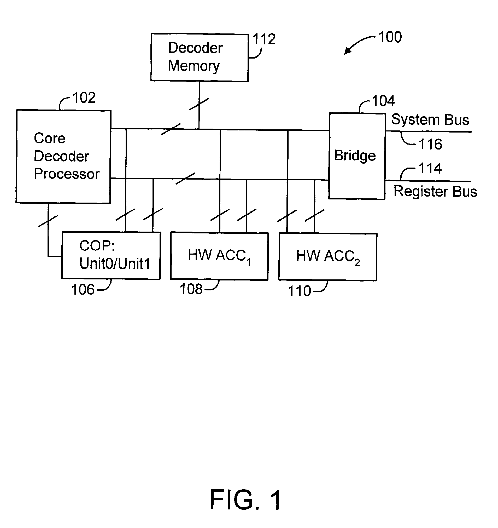
[0017]FIG. 1 is a functional block diagram of a computer system 100 according to an illustrative embodiment of the present invention. In the illustrative computer system 100 shown in FIG. 1, the computer system is a media decoding system. For purposes of illustration, aspects of the present invention will be described relative to such a media decoding system, and in particular, to a video decoding system. However, it is to be understood that aspects of the present invention can be implemented in any of a multitude of computer systems. Decoding system 100 includes a core decoder microprocessor 102, bridge module 104, co-processor 106, two hardware accelerators 108 and 110, decoder memory module 112, register bus 114 and system bus 116. Register bus 114 and system bus 116 communicate with an external host and external memory (not shown). In an illustrative embodiment, the co-processor comprises two independent and identical units. In an illustrative embodiment, the bridge module 104 i...


PUM


Abstract

A system and method for processing instructions in a computer system comprising a processor and a co-processor communicatively coupled to the processor. Instructions are processed in the processor in an instruction pipeline. In the instruction pipeline, instructions are processed sequentially by an instruction fetch stage, an instruction decode stage, an instruction execute stage, a memory access stage and a result write-back stage. If a co-processor instruction is received by the processor, the co-processor instruction is held in the core processor until the co-processor instruction reaches the memory access stage, at which time the co-processor instruction is transmitted to the co-processor.

Description

INCORPORATION BY REFERENCE OF RELATED APPLICATIONS[0001]The following U.S. Patent Applications are related to the present application and are hereby specifically incorporated by reference: patent application Ser. No. 10 / 114,679, entitled “METHOD OF OPERATING A VIDEO DECODING SYSTEM”; patent application Ser. No. 10 / 114,797, entitled “METHOD OF COMMUNICATING BETWEEN MODULES IN A DECODING SYSTEM”; patent application Ser. No. 10 / 114,886, entitled “MEMORY SYSTEM FOR VIDEO DECODING SYSTEM”; patent application Ser. No. 10 / 114,619, entitled “INVERSE DISCRETE COSINE TRANSFORM SUPPORTING MULTIPLE DECODING PROCESSES”; and patent application Ser. No. 10 / 114,798, entitled “VIDEO DECODING SYSTEM SUPPORTING MULTIPLE STANDARDS”; all filed on even date herewith. The following Provisional U.S. Patent Applications are also related to the present application and are hereby specifically incorporated by reference: Provisional Patent Application No. 60 / 369,144, entitled “VIDEO DECODING SYSTEM HAVING A PRO...

Claims


Application Information

Patent Timeline
Patent Type & Authority Patents(United States)
IPC IPC(8): G06F9/38G06T9/00H04N7/26H04N7/50H04N7/30
CPCG06F9/3861G06F9/3885H04N19/176H04N19/70H04N19/122H04N19/129H04N19/61H04N19/60H04N19/12H04N19/157H04N19/44H04N19/82H04N19/423H04N19/90
Inventor SO, KIMMING
Owner QUALCOMM INC
Learn More