System and method for air flow and EGR flow estimation
What is Al technical title?
Al technical title is built by PatSnap Al team. It summarizes the technical point description of the patent document.
a technology of air flow and air-fuel ratio, which is applied in the direction of machines/engines, liquid/fluent solid measurement, process and machine control, etc., can solve the problems of degrading air-fuel ratio control and inaccuracy estimation, and achieve the effect of improving accuracy
Inactive Publication Date: 2005-09-13
FORD GLOBAL TECH LLC
View PDF37 Cites 26 Cited by
Summary
Abstract
Description
Claims
Application Information
AI Technical Summary
This helps you quickly interpret patents by identifying the three key elements:
Problems solved by technology
Method used
Benefits of technology
[0009]An object of the invention claimed herein is to provide an exhaust gas recirculation measurement system and cylinder air charge estimation system with improve accuracy.
[0011]By using common signals for estimating EGR flow and cylinder air charge, a simplified structure and reduced cost system is obtained. Further, by using a fixed orifice area downstream of a control valve to recirculate exhaust gas along with pressure measurements upstream and downstream of the orifice, a more accurate EGR flow estimate is obtained. In particular, the estimation scheme does not have to account for the changing valve area, and thus less affects have to be included. Further yet, the present invention does not need to measure or infer exhaust manifold temperature or exhaust manifold pressure.
[0012]An advantage of the above aspect of the invention is that more accurate cylinder air charge estimate is obtained.
[0013]Another advantage of the above aspect of the invention is that the more accurate cylinder air estimate yields improved emissions at a reduced system cost.
Problems solved by technology
The inventors herein have recognized a disadvantage with the above system.
In particular, estimating EGR flow in this manner leads to estimation inaccuracies, due to valve area uncertainty.
This uncertainty may be caused by deposits in the valve.
Since inaccuracies in EGR flow directly affect estimated cylinder air charge, this leads to inaccuracies in calculated fuel injection amount and therefore may degrade air-fuel ratio control.
Method used
Image
Click on the blue label to locate the original text in one second.
Reading with bidirectional positioning of images and text.
Examples
Embodiment Construction
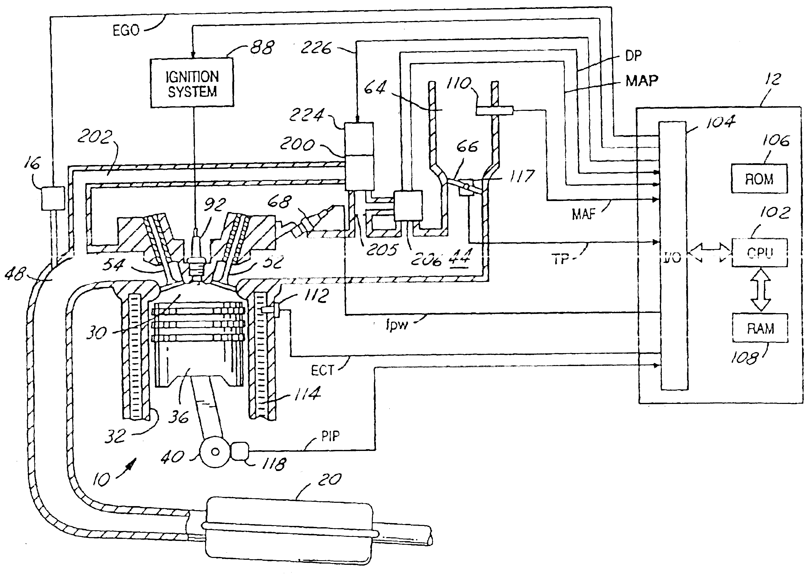
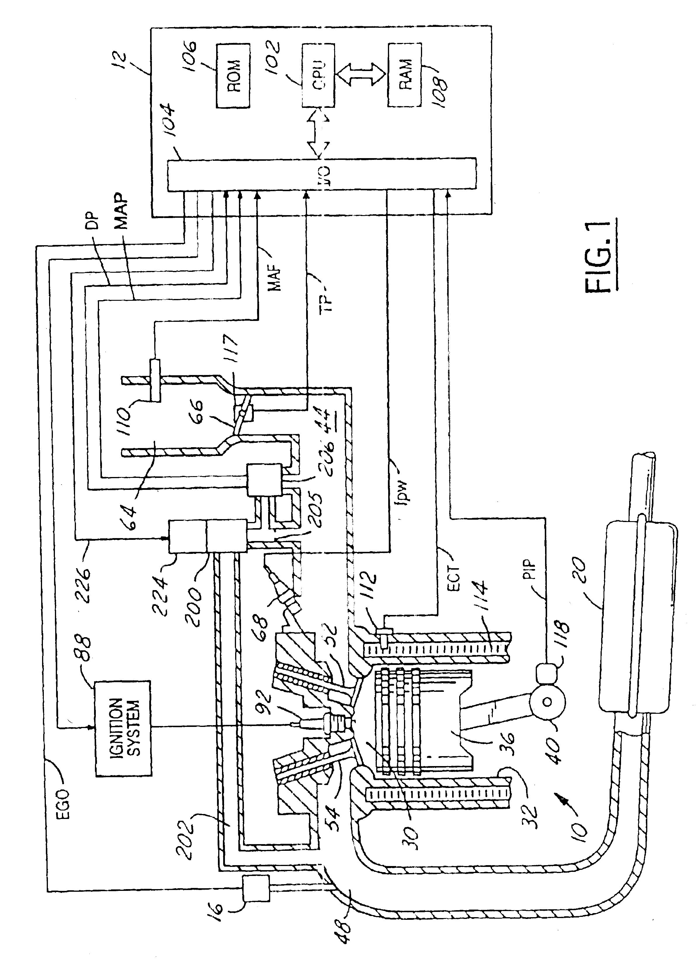
[0023]Internal combustion engine 10 comprising a plurality of cylinders, one cylinder of which is shown in FIG. 1, is controlled by electronic engine controller 12. Engine 10 includes combustion chamber 30 and cylinder walls 32 with piston 36 positioned therein and connected to crankshaft 40. Combustion chamber 30 communicates with intake manifold 44 and exhaust manifold 48 via respective intake valve 52 and exhaust valve 54. Exhaust gas oxygen sensor 16 is coupled to exhaust manifold 48 of engine 10 upstream of catalytic converter 20.
[0024]Intake manifold 44 communicates with throttle body 64 via throttle plate 66. Intake manifold 44 is also shown having fuel injector 68 coupled thereto for delivering fuel in proportion to the pulse width of signal (fpw) from controller 12. Fuel is delivered to fuel injector 68 by a conventional fuel system (not shown) including a fuel tank, fuel pump, and fuel rail (not shown). Engine 10 further includes conventional distributorless ignition syste...
PUM
Abstract
An exhaust gas recirculation system directs exhaust gasses from an exhaust manifold to an intake manifold of an internal combustion engine. The exhaust gasses travel from the exhaust manifold, first passing through a flow control valve and then through a measuring orifice before entering the intake manifold. Pressure upstream of the orifice is used, along with correction pressure downstream of the orifice, to measure and control exhaust gas flow. Further, manifold pressure is determined from downstream pressure and the used along with the measured exhaust gas flow to calculated a cylinder air charge amount.
Description
CROSS REFERENCE TO RELATED APPLICATIONS[0001]This application is a divisional of Ser. No. 09 / 539,227 filed Mar. 30, 2000, now U.S. Pat. No. 6,609,058 which is a continuation-in-part of application Ser. No. 09 / 226,681, filed Jan. 11, 1999 now U.S. Pat. No. 6,308,694 and application Ser. No. 09 / 517,201, filed Mar. 2, 2000, now U.S. Pat. No. 6,321,732 which is, in turn, a continuation-in-part of Ser. No. 09 / 226,681, filed Jan. 11, 1999, now U.S. Pat. No. 6,308,694 and Ser. No. 09 / 090,125, filed Jun. 4, 1998 now U.S. Pat. No. 6,138,504. This application hereby expressly incorporates by reference the entire specification of Ser. No. 09 / 226,681, filed Jan. 11, 1999, Ser. No. 09 / 517,201 filed Mar. 2, 2000, and Ser. No. 09 / 090,125, filed Jun. 4, 1998.FIELD OF THE INVENTION[0002]The present invention relates to an air / fuel ratio control system for an internal combustion engine where air flow and exhaust gas recirculation flow are calculated from pressure sensors.BACKGROUND OF THE INVENTION[0...
Claims
Application Information
Patent Timeline
Application Date:The date an application was filed.
Publication Date:The date a patent or application was officially published.
First Publication Date:The earliest publication date of a patent with the same application number.
Issue Date:Publication date of the patent grant document.
PCT Entry Date:The Entry date of PCT National Phase.
Estimated Expiry Date:The statutory expiry date of a patent right according to the Patent Law, and it is the longest term of protection that the patent right can achieve without the termination of the patent right due to other reasons(Term extension factor has been taken into account ).
Invalid Date:Actual expiry date is based on effective date or publication date of legal transaction data of invalid patent.