Subea pipeline blockage remediation method

a technology for subea pipelines and remediation methods, applied in the direction of manufacturing tools, borehole/well accessories, insulation, etc., can solve the problems of increasing the temperature of seawater outlet, increasing the cooling, and literally continuing to grow additional hydrate blockage, so as to minimize the disturbance of the pipeline and increase the outlet temperature of seawater

Inactive Publication Date: 2005-09-06
BAUGH BENTON F
View PDF14 Cites 75 Cited by
  • Summary
  • Abstract
  • Description
  • Claims
  • Application Information

AI Technical Summary

Benefits of technology

[0011]A second object of the present invention is to provide a method of removing the hydrate or paraffin without requiring that the pressure integrity of the pipeline be compromised.
[0012]A third object of the present invention is to provide for recirculation of seawater to allow the heat not absorbed into the pipeline to increase the inlet temperature to the seawater heating means—thereby increasing the outlet temperature of the seawater.
[0013]Another object of the present invention is to provide a means for applying heat to the outer surface of a subsea pipeline without uncovering the pipeline to minimize the disturbance to the pipeline.
[0014]Another object of the present invention is to provide means for applying heat to the outer surface of a subsea pipeline without uncovering the pipeline so that the insulating effects of the covering will retain the heat in the pipeline.

Problems solved by technology

There is a tendency for hydrates to form in the pipelines departing from a subsea gas well, especially on well startup.
When a subsea pipeline valve is opened, the gas expansion can cause substantial additional cooling.
This means that not only can the expansion of this gas keep the formed hydrate cool, but can literally continue to grow additional hydrate blockage.
It is difficult to tell where the hydrates are actually located in deepwater pipelines, especially when the pipelines are buried.
Hydrates formed like this can last for weeks or months, with a substantial loss of gas flow and therefore revenue to the owner of the pipelines and subsea wells.
In some cases the paraffin will release from the subsea pipeline inner diameter without a pig and cause a blockage.
This is an expensive operation, and in some cases the blockage can be 10 to 20 miles away.
Removal by use of coiled tubings can be further complicated if the pipeline has bends in it, making passage of the coiled tubing difficult if not impossible.

Method used


Image

  • Subea pipeline blockage remediation method
  • Subea pipeline blockage remediation method
  • Subea pipeline blockage remediation method

Examples


Embodiment Construction

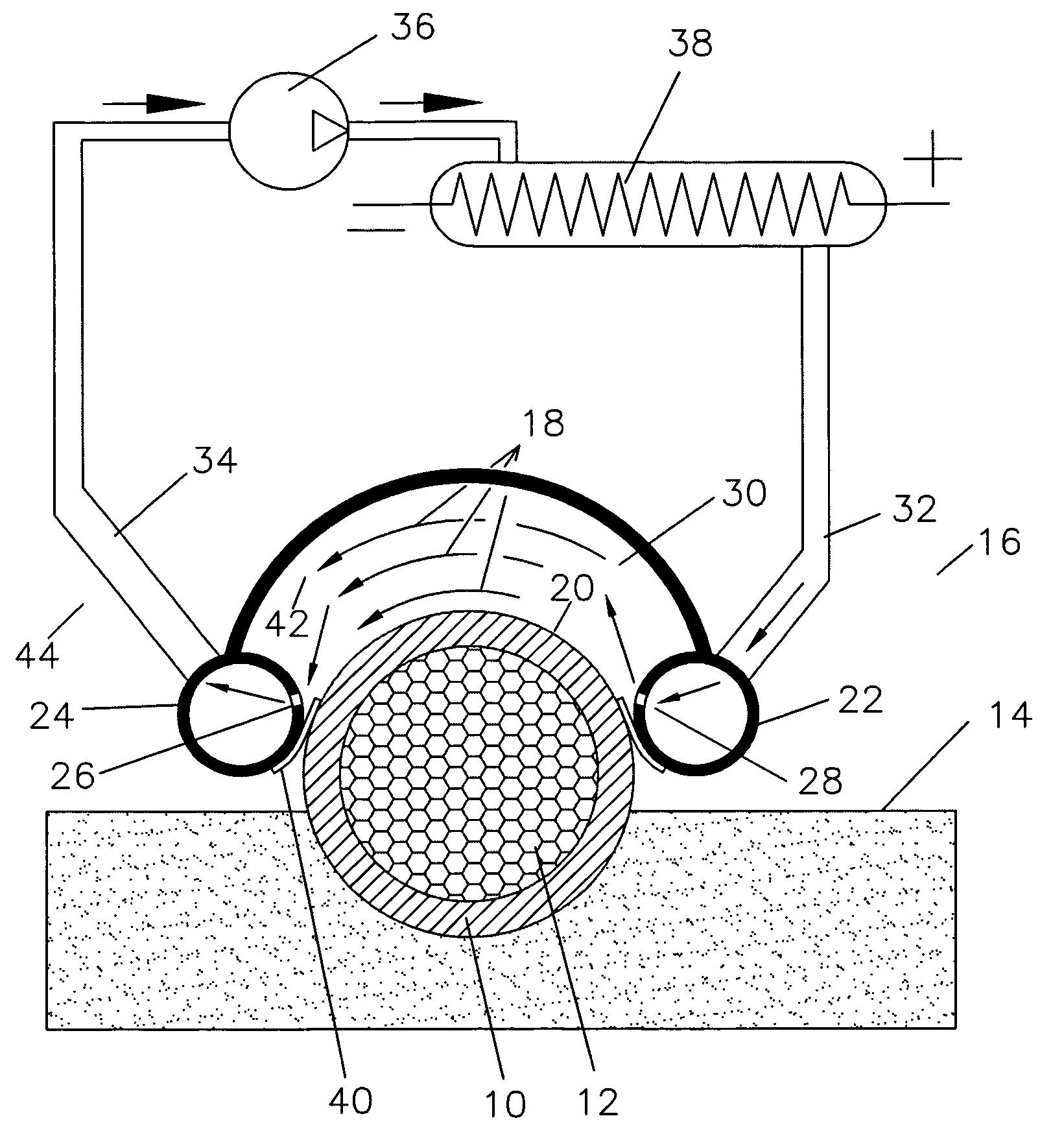
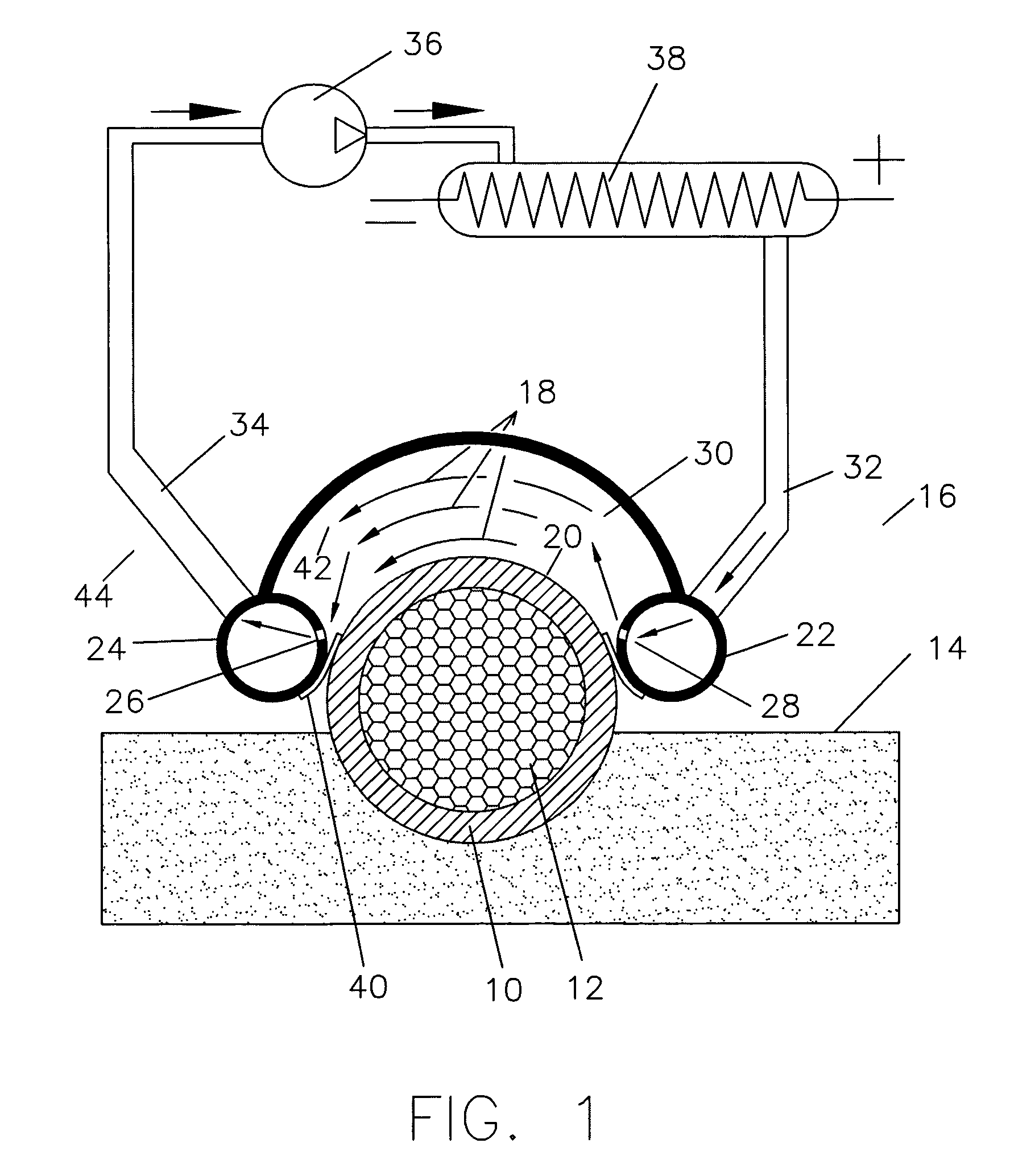
[0028]Referring now to FIG. 1, a subsea pipeline 10 has a blockage indicated at 12. The subsea pipeline 10 is setting on the seafloor 14 and is covered by seawater 16 which may be as cold as 32° F. Arrows 18 indicate the flowing of heated seawater across the upper portion 20 of the subsea pipeline 10 for the purpose of disassociating the pipeline blockage 12. The disassociation may be melting a hydrate, melting a paraffin blockage, or softening a paraffin blockage to the point that it will flow.

[0029]Two tubes 22 and 24 run parallel to the subsea pipeline and have a plurality of holes 26 and 28 which direct heated seawater into the circulation chamber 30 or out of the circulation chamber 30 respectively. Line 32 feeds heated seawater into tube 22 and return line 34 draws the seawater out of tube 24. The return line 34 leads to pump 36 and then to heating element 38 and back to tube 32. The heated seawater which is introduced into the combustion chamber by tube 22 is somewhat cooled ...


PUM

PropertyMeasurementUnit
temperatureaaaaaaaaaa
electrical resistanceaaaaaaaaaa

Abstract

The method of taking a remotely operated vehicle to the ocean floor to land on and move along a subsea pipeline above or below the seafloor and repeatedly circulate seawater which has been heated electrically, mechanically, or chemically across the outer surface of the pipeline to melt hydrates or paraffins which have formed on the inside of the pipeline.

Description

BACKGROUND OF THE INVENTION[0001]The field of this invention is that of removing blockages in remote subsea pipeline, typically from subsea gas well installations.[0002]Hydrates are a porous solid which is formed primarily of water with a mixture of gases. It is effectively similar to ice. There is a tendency for hydrates to form in the pipelines departing from a subsea gas well, especially on well startup.[0003]The temperature of seawater at depths will often approach 32° F., with the temperature in non-flowing pipelines being the same. When a subsea pipeline valve is opened, the gas expansion can cause substantial additional cooling. In these cold and high pressure conditions, hydrates of the gas and water can quickly form.[0004]Frequently when the hydrate forms, it forms a blockage, the blockage will be somewhat porous. At that time, a high pressure will exist on the upstream side and a lower pressure will exist on the downstream side of the blockaged. This means that additional ...

Claims


Application Information

Patent Timeline
Patent Type & Authority Patents(United States)
IPC IPC(8): F16L53/00B08B7/00B08B9/02E21B37/00F16L53/32
CPCB08B7/0071B08B9/027E21B37/00F16L53/002F16L53/32
Inventor BAUGH, BENTON F.
Owner BAUGH BENTON F
Why Eureka
Try Eureka