
Rendering images utilizing adaptive error diffusion

a technology of error diffusion and image data, applied in image enhancement, digitally marking record carriers, instruments, etc., can solve the problems of many ordered dither digital halftoning methods suffering from low frequency artifacts, low frequency artifacts are very noticeable, etc., and achieve the effect of reducing artifacts and being easy to implemen

Active Publication Date: 2005-08-30
SENSHIN CAPITAL
View PDF12 Cites 25 Cited by
  • Summary
  • Abstract
  • Description
  • Claims
  • Application Information

AI Technical Summary

Benefits of technology

[0012]It is the primary object of this invention to provide a method for generating a halftone image from a digitized continuous tone input image that provides adjustment of the local contrast of the resulting halftone image, minimizes artifacts and is easily implemented.

Problems solved by technology

However, many display devices, such as laser and ink jet printers, print only in a binary fashion.
Furthermore, some image format standards only allow binary images.
Besides allowing only binary images, some image format standards and some displays only allow images of a limited number of pixels.
Some WAP devices have screens that are very limited in terms of the number of pixels.
Many ordered dither digital halftoning methods suffer from low frequency artifacts.
Because the human vision system has greater sensitivity at low frequencies (less than 12 cycles / degree), such low frequency artifacts are very noticeable.
Although the error diffusion method presents an improvement over many ordered dither methods, artifacts are still present.
Other known artifacts produced by the error diffusion method include artifacts called “worms” and “snowplowing” which degrade image quality.
The improvements disclosed by Eschbach do not allow the control of the edge enhancement by controlling the high frequency portion of the error.
Also, the improvements disclosed by Eschbach do not introduce parameters that can be selected to produce the image of the highest perceptual quality at a specific output device.

Method used


Image

  • Rendering images utilizing adaptive error diffusion
  • Rendering images utilizing adaptive error diffusion
  • Rendering images utilizing adaptive error diffusion

Examples


embodiment

Sample Embodiment

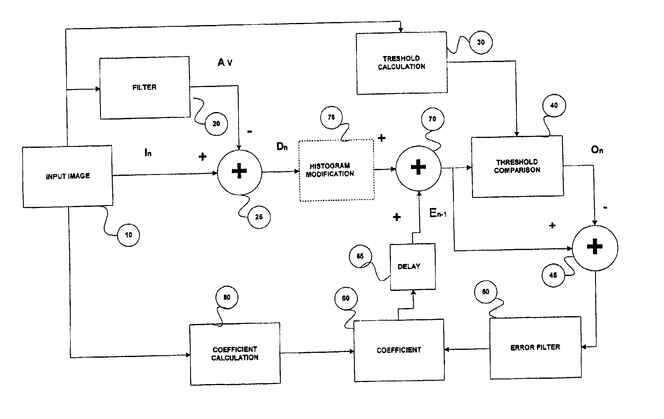
[0043]In a specific embodiment, shown in FIG. 2, the output of the filtering block 20, Avn, is given by Equation (2). The threshold calculation 30 is a function of the output of the filtering block 20 and is given by

t( . . . ,Ik, . . . , I.n, . . . )=C0Avn  (7)

which is the same function as in Equation 4 when the output of the filtering block 20, Avn, is given by Equation (2). The output of the coefficient calculation block 80 depends on the output of the filtering block 20, Avn, and the difference Dn and is given by

C1+C2{abs((Dn−Avn) / Avn)}  (8)

When the output of the filtering block 20, Avn, is given by Equation (2), Equation (8) is the same as Equation (6).

[0044]Histogram equalization is included after the summing node 25. The processing of the input image pixels 10 occurs as described in the preceding section.

[0045]The value of N in Equation (2) (the extent of the filter), C0, C1, and C2 (first, second parameters and third parameters) can be selected to produce the...


PUM


Abstract

An adaptive halftoning method where the difference between a digital image and a filtered digital image is introduced into the system on a pixel by pixel basis is disclosed. In this method, each input difference pixel has a corresponding error value of the previous pixel added to the input value at a summing node, resulting in modified image difference data; the modified image difference data is passed to a threshold comparator where the modified image difference data is compared to a threshold value, the threshold value varying according to the properties of the digital image, to determine the appropriate output level; the output level is subtracted from the modified image difference value to produce the input to an error filter; the output of the error filter is multiplied by an adaptation coefficient, where the adaptation coefficient varies according to the properties of the digital image, to generate the error level for the subsequent input pixel; and, the cyclical processing of pixels is continued until the end of the input data is reached.

Description

BACKGROUND OF THE INVENTION[0001]1. Field of the Invention[0002]The present invention relates to the rendering of digital image data, and in particular, to the binary or multilevel representation of images for printing or display purposes[0003]2. Background Description[0004]Since images constitute an effective means of communicating information, displaying images should be as convenient as displaying text. However, many display devices, such as laser and ink jet printers, print only in a binary fashion. Furthermore, some image format standards only allow binary images. For example, the WAP1.1 (Wireless Application Protocol) protocol specification allows only for one graphic format, WBMP, a one (1) bit version of the BMP (bitmap) format. Besides allowing only binary images, some image format standards and some displays only allow images of a limited number of pixels. In the WAP 1.1 standard, a WBMP image should not be larger than 150×150 pixels. Some WAP devices have screens that are...

Claims


Application Information

Patent Timeline
IPC IPC(8): H04N1/405B41J2/52G06T3/40G06T5/20G06T5/40
CPCH04N1/4053
Inventor GORIAN, IZRAIL S.THORNTON, JAY E.PINEAU, RICHARD A.
Owner SENSHIN CAPITAL
Learn More