
Optimization of a pulse sequence for a magnetic resonance system

a magnetic resonance system and pulse sequence technology, applied in the direction of reradiation, measurement using nmr, instruments, etc., can solve the problems of higher power consumption, known noise development, imposing greater demands on gradient coils and additional hardware, and achieve the effect of reducing expenditur

Active Publication Date: 2014-08-21
SIEMENS HEALTHCARE GMBH
View PDF5 Cites 44 Cited by
  • Summary
  • Abstract
  • Description
  • Claims
  • Application Information

AI Technical Summary

Benefits of technology

The invention aims to improve the efficiency and reduce the noise of magnetic resonance imaging (MRI) systems. It does this by optimizing the coding of gradient pulses, which are used to generate the pulse sequences used in MRI. By doing so, the system can generate quieter pulse sequences and reduce the deviation of gradients, which can lead to better image quality. Additionally, the invention prevents unnecessary gradient activities and minimizes flow artifacts caused by moving substances, such as blood flow. Overall, this approach makes MRI more effective and reliable.

Problems solved by technology

In particular, such a high edge steepness contributes to the known noise development during the switching of the gradients.
In addition, steep edges of the gradients lead to a higher power consumption and additionally impose greater demands on the gradient coils and the additional hardware.
The rapidly changing gradient fields lead to distortions and oscillations in the gradient coils and to the transfer of these energies to the housing.

Method used


Image

  • Optimization of a pulse sequence for a magnetic resonance system
  • Optimization of a pulse sequence for a magnetic resonance system
  • Optimization of a pulse sequence for a magnetic resonance system

Examples


Embodiment Construction

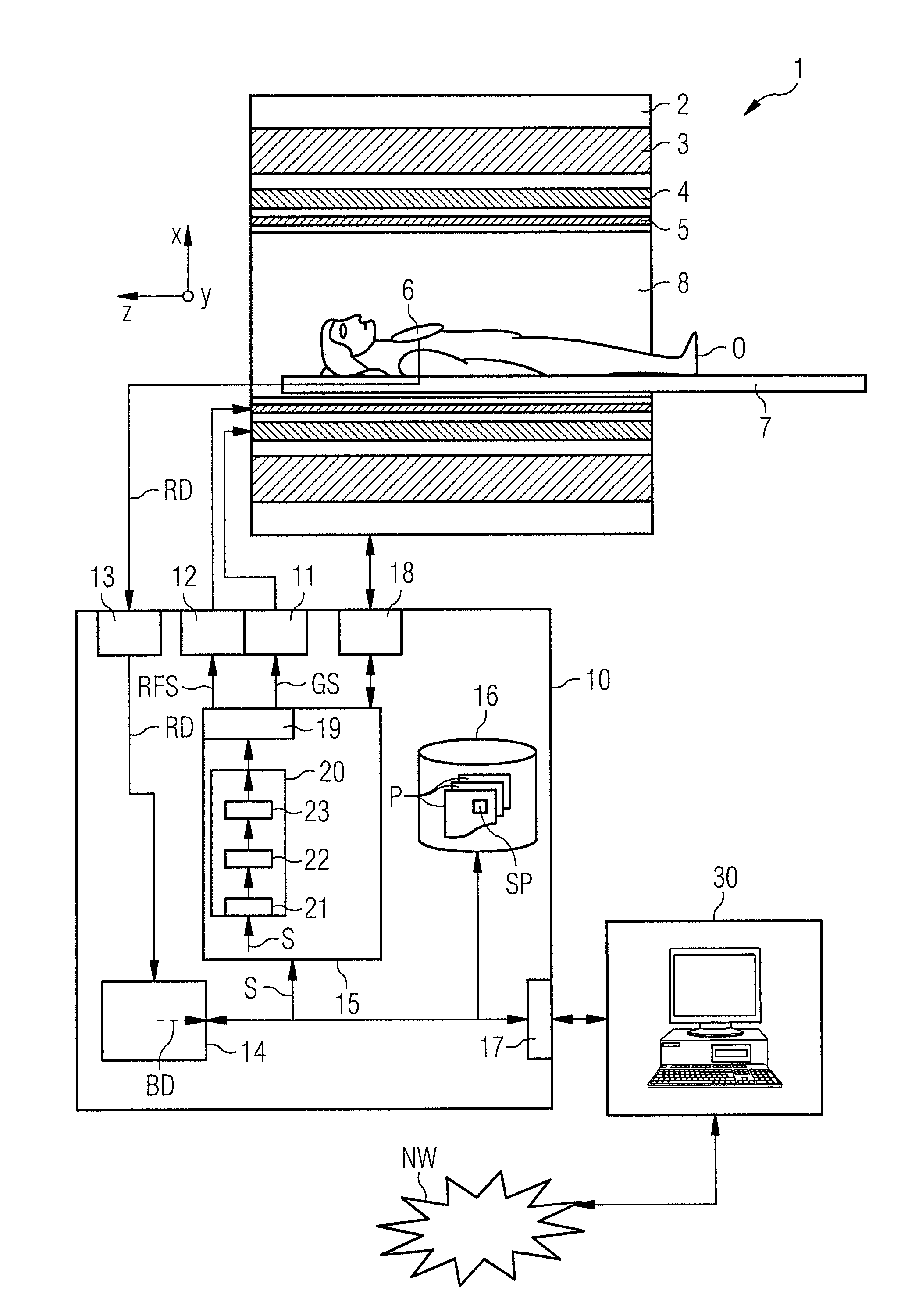
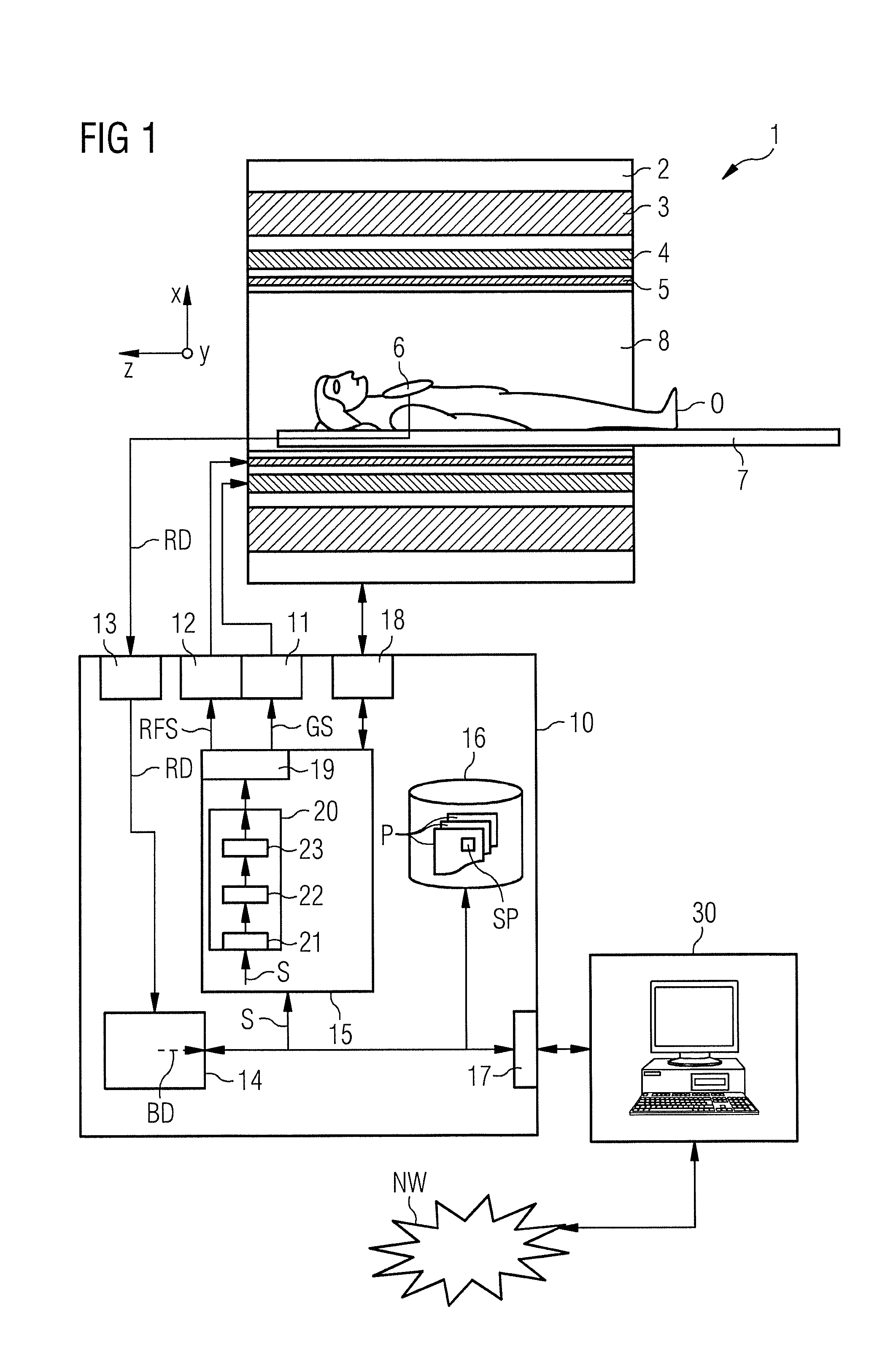
[0071]A magnetic resonance system 1 according to the invention is schematically depicted in FIG. 1. The actual magnetic resonance scanner 2 has an examination space 8 or patient tunnel 8 located therein. A bed 7 can be driven into this patient tunnel 8 so that a patient O or test subject lying thereupon during an examination can be supported at a defined position within the magnetic resonance scanner 2 relative to the magnet system and radio-frequency system arranged therein, can also be moved between different positions during a measurement.

[0072]Significant components of the magnetic resonance scanner 2 are a basic field magnet 3, a gradient system 4 with magnetic field gradient coils to generate magnetic field gradients in the x-, y- and z-directions, and a whole-body radio-frequency coil 5. The magnetic field gradient coils in the x-, y- and z-directions are controllable independently of one another so that gradients can be applied in arbitrary logical spatial directions (for ex...


PUM


Abstract

In a method and a pulse sequence optimization device to determine a pulse sequence for a magnetic resonance system, a pulse sequence is selected for optimization that includes a number of radio-frequency pulses and a number of gradient pulses chronologically coordinated therewith. An automatic analysis of the pulse sequence takes place to identify fixed point / time periods in the pulse sequence that are to be left unmodified, and modifiable time intervals in the pulse sequence that may be optimized. An automatic optimization of gradient pulses in the modifiable time intervals takes place according to a predetermined optimization criterion, while keeping the length of modifiable time intervals constant.

Description

BACKGROUND OF THE INVENTION[0001]1. Field of the Invention[0002]The present invention concerns a method to optimize a pulse sequence for operating a magnetic resonance system. Moreover, the invention concerns a method to operate a magnetic resonance system using such an optimized pulse sequence, as well as a pulse sequence optimization device and a magnetic resonance system designed to implement this method.[0003]2. Description of the Prior Art[0004]In a magnetic resonance system—also called a magnetic resonance tomography system—the body to be examined is typically exposed to a relatively high basic magnetic field (for example of 1, 5, 3 or 7 Tesla) with the use of a basic field magnet system. A magnetic field gradient is additionally applied by a gradient system. Via suitable antenna devices, radio-frequency excitation signals (RF signals) are then emitted from a radio-frequency transmission system, such radio-frequency excitation signals causing nuclear spins of specific atoms th...

Claims


Application Information

Patent Timeline
Patent Type & Authority Applications(United States)
IPC IPC(8): G01R33/54
CPCG01R33/543G01R33/56509
Inventor GRODZKI, DAVIDHEISMANN, BJOERN
Owner SIEMENS HEALTHCARE GMBH
Learn More