
Imaging tomography device with at least two beam detector systems, and method to operate such a tomography device

Inactive Publication Date: 2006-05-02
SIEMENS HEALTHCARE GMBH
View PDF9 Cites 34 Cited by
  • Summary
  • Abstract
  • Description
  • Claims
  • Application Information

AI Technical Summary

Benefits of technology

[0007]An object of the invention is to improve the image quality in a tomography apparatus of the cited type.
[0021]In the tomography apparatus according to the invention both acquisition systems can be arranged in a common plane. This has the advantage that artifacts as a result of an unwanted movement of the patient (breathing, etc.) are minimized. However, embodiments are also possible in which the acquisition systems are separated from one another and / or can be positioned separated from one another in the direction of the rotation axis.

Problems solved by technology

Conventionally, this has been attempted to be achieved by increasing the rotation speed of the acquisition system, however the acceleration forces, and the mechanical problems resulting therefrom, increase significantly with additional rotation speed.
In x-ray computed tomography, unwanted artifacts can occur in the CT image if scattered x-ray quanta also reach the detector in addition to the primary quanta, due to x-ray quanta scattered in the examination subject.
Additionally, such an increase of the collimator height would be very difficult mechanically to control, and would in addition increase the costs for the detector system.

Method used


Image

  • Imaging tomography device with at least two beam detector systems, and method to operate such a tomography device
  • Imaging tomography device with at least two beam detector systems, and method to operate such a tomography device
  • Imaging tomography device with at least two beam detector systems, and method to operate such a tomography device

Examples


Embodiment Construction

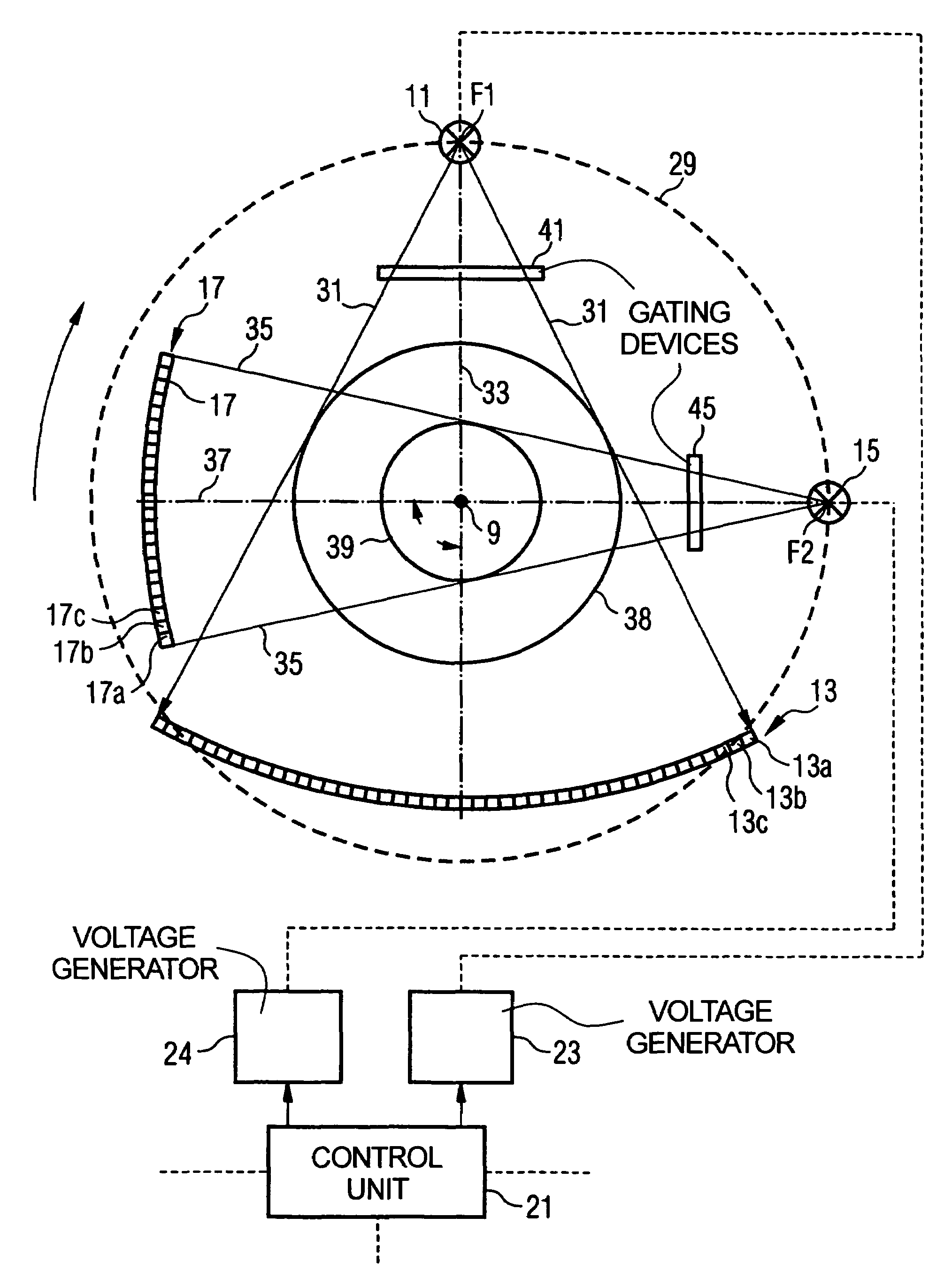
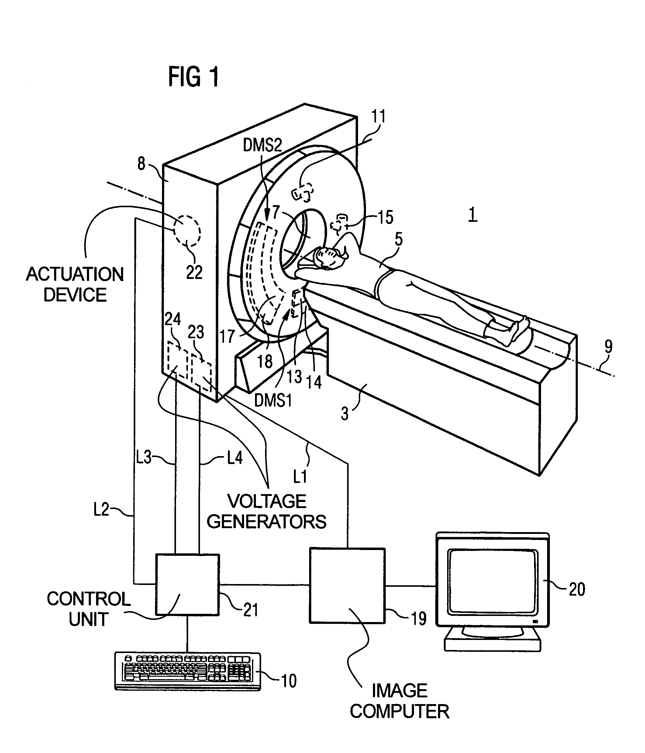
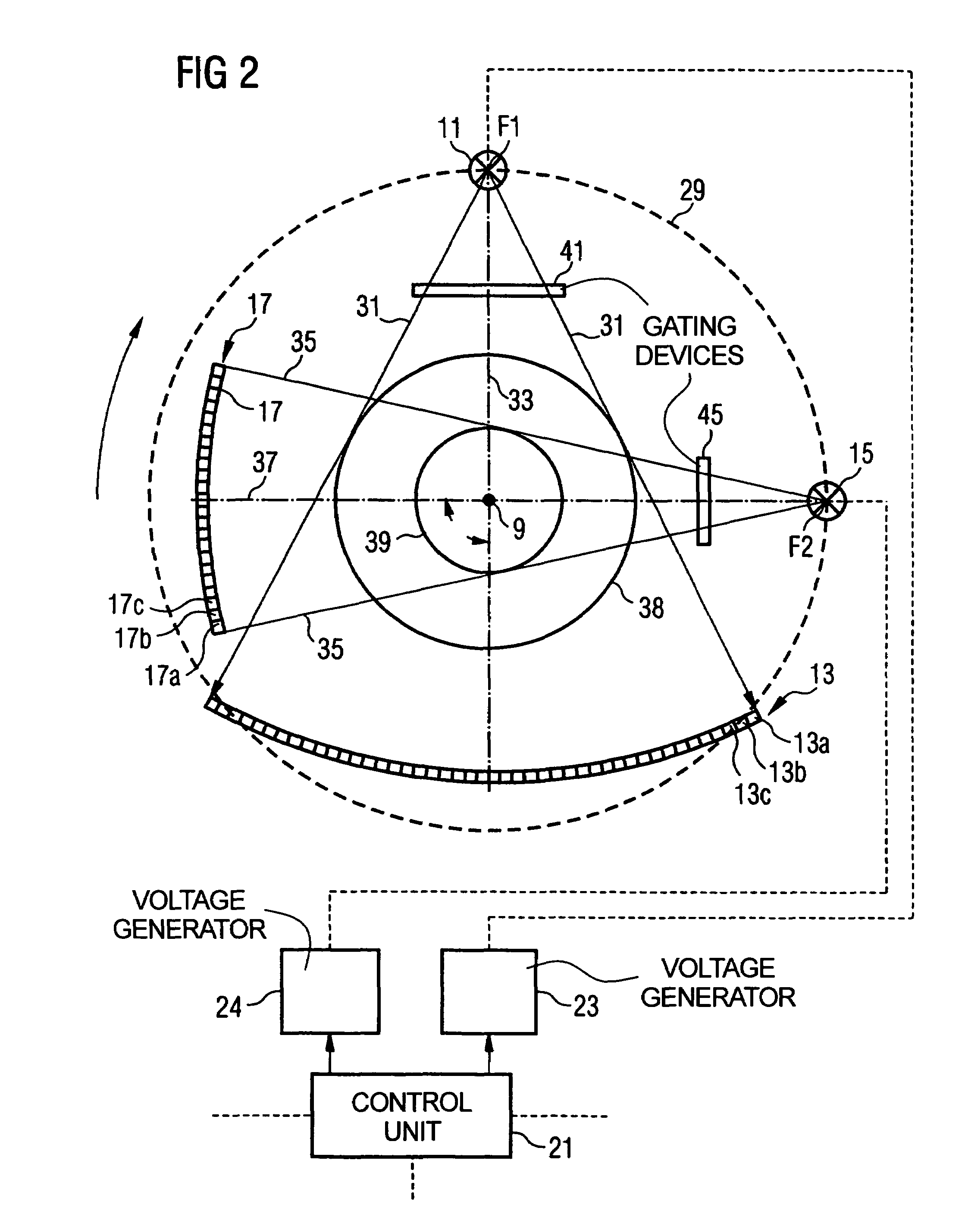
[0036]Three exemplary embodiments of a tomography device according to the invention are subsequently explained in detail in FIGS. 1 through 7. FIGS. 1 through 7 also serve to explain the method according to the invention.

[0037]FIG. 1 shows a first exemplary embodiment of a tomography apparatus 1 (here an x-ray computed tomography apparatus) with an associated positioning device 3 for exposure and positioning of an examination subject 5, for example a patient. The patient 5 with the desired examination region or scan region can be inserted into an opening 7 (diameter 70 cm) in the housing 8 of the tomography apparatus 1 by means of a movable table top of the positioning device 3. Inside the housing 8, a gantry (not visible) is mounted so as to be rotated with high speed around a rotation axis 9 running through the patient. Moreover, for a spiral scan, a continuous axial feed is effected with the positioning device 3.

[0038]A control unit 10 is provided for operation of the tomography ...


PUM


Abstract

An imaging tomography apparatus, in particular x-ray computed tomography apparatus, for examining an examination subject has at least two acquisition systems, each having a radiator and a data acquisition unit to detect the radiation originating from the associated radiator. The acquisition systems are capable of rotating around a common rotation axis with a constant angular separation in the azimuthal direction. Radiation from only one of the radiators is permitted to reach the examination subject during the rotation of the acquisition systems. Signal contributions by the x-ray tubes not supplying this data acquisition unit with primary radiation arrive are prevented, the projection data set generated by one of the data acquisition units.

Description

BACKGROUND OF THE INVENTION[0001]1. Field of the Invention[0002]The present invention concerns an imaging tomography apparatus and a method for operating such an apparatus, in particular an x-ray computed tomography apparatus, of the type having at least a first acquisition system, with a first radiator and a first data acquisition unit for detection of radiation originating from the first radiator, and a second acquisition system, with a second radiator and a second data acquisition unit for detection of radiation originating from the second radiator, wherein both acquisition systems are capable of rotating around a common rotation axis with a constant angular separation in the azimuthal direction.[0003]2. Description of the Prior Art[0004]Tomography apparatuses of the above type are known, for example, from U.S. Pat. Nos. 4,991,190, 4,384,359, 4,196,352, 5,966,422, and 6,421,412. An advantage that such tomography apparatuses with a multiple acquisition systems exhibit in compariso...

Claims


Application Information

Patent Timeline
IPC IPC(8): G01N23/00A61B6/03G01N23/04
CPCA61B6/032A61B6/4014G01N23/046G01N2223/612G01N2223/419
Inventor BRUDER, HERBERTHOELZEL, ARNESTIERSTORFER, KARL
Owner SIEMENS HEALTHCARE GMBH
Learn More