
Inverter circuit of microwave oven

a technology of inverter circuit and microwave oven, which is applied in the direction of electric/magnetic/electromagnetic heating, process and machine control, etc., can solve the problems of difficult control of inverter circuit correctly, slow program processing time of micom, and high cost of photo couplers, so as to reduce the unit manufacturing cost of production

Active Publication Date: 2005-08-30
LG ELECTRONICS INC
View PDF5 Cites 4 Cited by
  • Summary
  • Abstract
  • Description
  • Claims
  • Application Information

AI Technical Summary

Benefits of technology

[0018]An object of the present invention is to provide an inverter circuit of a microwave oven provided with inexpensive devices, for decreasing the unit manufacturing cost of production.

Problems solved by technology

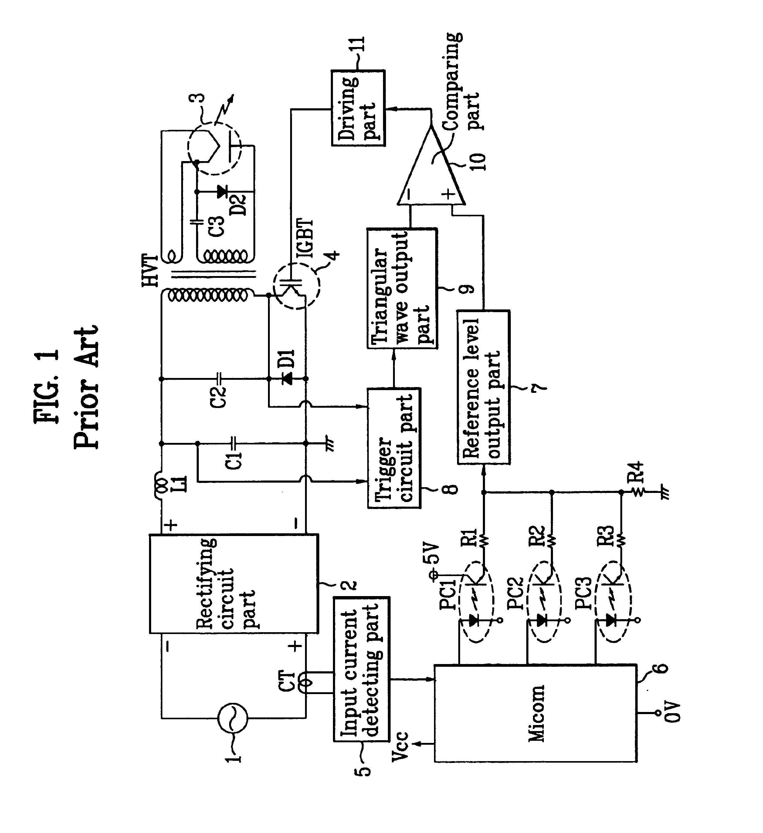
First, the inverter circuit of the microwave oven according to the related art requires the plurality of photo couplers as means of controlling the output, so that the unit manufacturing cost of production (microwave oven) is increased in that the photo coupler is expensive device.
Also, the micom receives the output (present current) of the input current detecting part by feedback, and controls the output of the inverter circuit, whereby a program processing time of the micom is slow, and it is difficult to control the inverter circuit correctly.

Method used


Image

  • Inverter circuit of microwave oven
  • Inverter circuit of microwave oven
  • Inverter circuit of microwave oven

Examples


Embodiment Construction

[0037]Reference will now be made in detail to the preferred embodiments of the present invention, examples of which are illustrated in the accompanying drawings.

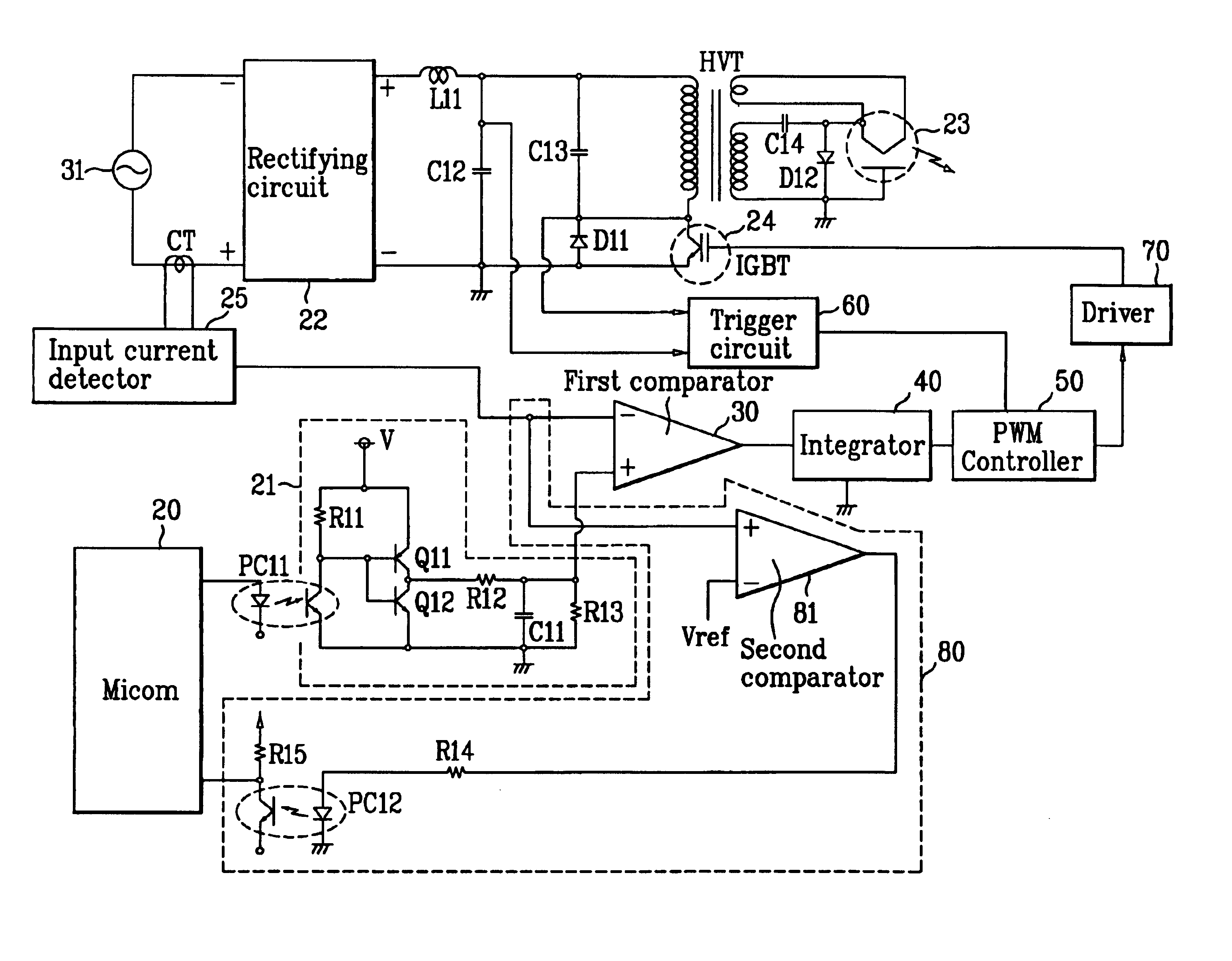
[0038]FIG. 3 illustrates an inverter circuit of a microwave oven according to the present invention. Referring to FIG. 3, the inverter circuit for the microwave oven according to the present invention is provided with a rectifying circuit 22 for rectifying an AC power from a power source 31 to be connected to both sides of the power source 31. Then, both output terminals of the rectifying circuit 22 are respectively connected to a primary side coil of a high voltage transformer HVT (omission of a reference number) and a switching device IGBT 24. That is, a non-inversion (+) terminal of the rectifying circuit 22 is connected to an upper side of the primary side coil of the HVT, and an inversion (−) terminal of the rectifying circuit 22 is connected to the switching device 24.

[0039]Also, a secondary side coil of the HVT is con...


PUM


Abstract

An inverter circuit of a microwave oven employs a technique which decreases the unit manufacturing cost of production and controls an output of a magnetron correctly. The invert circuit includes a micom outputting a reference voltage preset by a user; an input current detector converting a current provided from the power source to a voltage level; and comparator comparing an output signal of the input current detector with the reference voltage; an integrator increasing or decreasing a level of an output signal for the comparator a trigger circuit connected to the high voltage transformer, and generating a trigger signal; and a PWM controller receiving an output signal of the integrator and an output al of the trigger circuit, for controlling drive of the magnetron.

Description

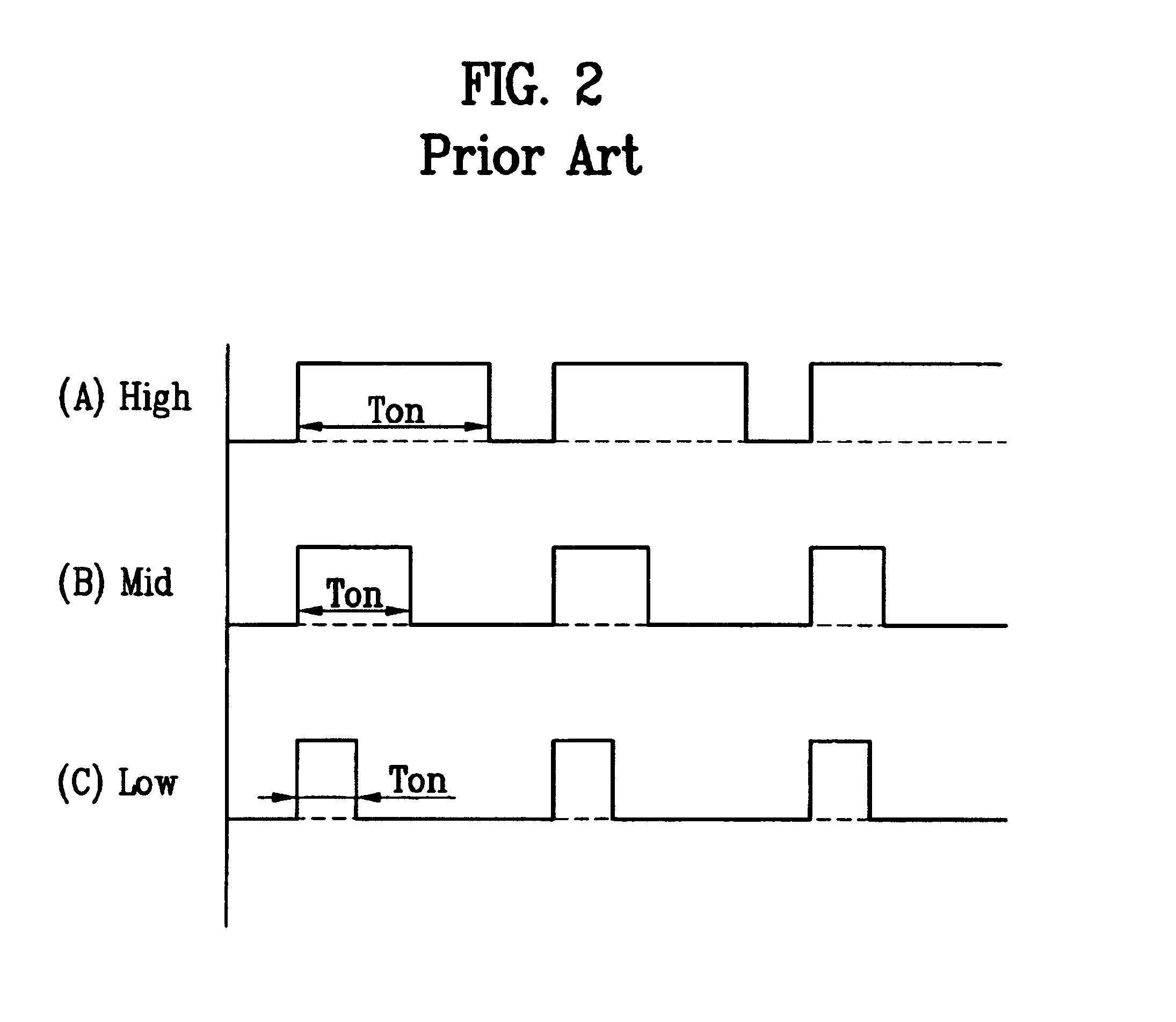
[0001]This application claims the benefit of the Korean Application No. P2002-0087116 filed on Dec. 30, 2002, which is hereby incorporated by reference.BACKGROUND OF THE INVENTION[0002]1. Field of the Invention[0003]The present invention relates to a microwave oven, and more particularly, to an inverter circuit of a microwave oven driving a magnetron in an inverter system.[0004]2. Background of the Related Art[0005]Home appliances for cooking comprise a gas range, a gas oven range, a microwave oven and an electric oven. Among the home appliances for cooking, the microwave oven heats an object provided in a cavity with a microwave oscillated in a magnetron MGT therein. Generally, the microwave oven uses an inverter circuit to control drive of the magnetron.[0006]An inverter circuit of a microwave oven according to the related art will be described as follows.[0007]As shown in FIG. 1, the inverter circuit of the microwave oven according to the related art is provided with a rectifying...

Claims


Application Information

Patent Timeline
Patent Type & Authority Patents(United States)
IPC IPC(8): H05B6/66H05B6/68
CPCH05B6/66H05B6/68
Inventor I, MIN GIHAN, SUNG JINSHIN, DONG MYUNG
Owner LG ELECTRONICS INC
Learn More