Radiation-Cured Coatings

a technology of coating and curing process, applied in the direction of plasma technique, electrical apparatus, electric discharge tube, etc., can solve the problems of contaminating the pump, contaminating the pump, and other problems inherent in the process, so as to improve the barrier to oxygen, other gases, odour or taint, and improve the effect of curing speed

Inactive Publication Date: 2011-09-08
CAMVAC
View PDF9 Cites 2 Cited by
  • Summary
  • Abstract
  • Description
  • Claims
  • Application Information

AI Technical Summary

Benefits of technology

[0013]The electron flux is directed at the substrate either simultaneously or sequentially with delivery of the precursor material. In the former case, curing is preferably initiated spatially and temporally concurrently with delivery of the precursor material to the substrate, which avoids the need for the electron flux to penetrate the condensed precursor material in order to cure it.
[0016]Embodiments of the invention serve to reduce the risk of re-evaporation and “snowing” and produce a more homogenously cured coating. The tendency to “blocking” is reduced, and the substrate surface does not need further treatment before recoating. The process of the invention can therefore be run at higher line speeds, thereby reducing unit production costs.
[0020]The substrate may comprise an aluminium or aluminium oxide coated plastic film and may be coated with radiation cured material and recoated with a further layer of aluminium or aluminium oxide to produce an enhanced barrier to oxygen, other gases, water vapour, odour or taint.
[0022]The adhesion of the various layers of the product may be sufficient to prevent delamination during any subsequent conversion or use.

Problems solved by technology

However, the existing sequential processes of vacuum condensation and curing of polymer precursors have a number of drawbacks / risks, associated with impurities in the commercial grades of raw materials used, particularly for the substrate, or inherent in the process itself.
However, other problems inherent in the process are more difficult to overcome.
This vapour can then potentially contaminate the pumps, or become entrained with the moving web, re-condense on the surface of the cured coating as an uncured, and therefore weak surface layer (giving poor adhesion of any subsequent coatings applied to the material).
b) It is known that as the curing of the condensate only takes place within the zone of irradiation, at high line speeds (essential for an economically viable process), 100% polymerisation is difficult to achieve, particularly at the surface adjacent to the substrate and thus furthest from the radiation source.
Increasing the radiation flux to increase curing can result in over-curing and embrittlement of the top surface of the coating closest to the radiation source, whilst still leaving the bottom surface under-cured and with poor adhesion.
It is difficult therefore to achieve the homogeneity of curing through the thickness of the coating desirable for good mechanical strength, adhesion or barrier.
c) It is known that if the precursor vapour or atomised liquid is passed through the radiation flux prior to delivery on the substrate, it can partially polymerise, giving rise to a non-homogeneous and mechanically weak coating with poor adhesion.
d) It is known that if the coating is cured using a charged radiation flux, such as a high energy electron beam, the resultant coated web can “block” (i.e. stick to itself) when it is wound up into a roll, and then later tear when it is unwound.
The risk of damage on unwinding is further accentuated by poor homogeneity through the coating.

Method used


Image

  • Radiation-Cured Coatings
  • Radiation-Cured Coatings
  • Radiation-Cured Coatings

Examples


example 1

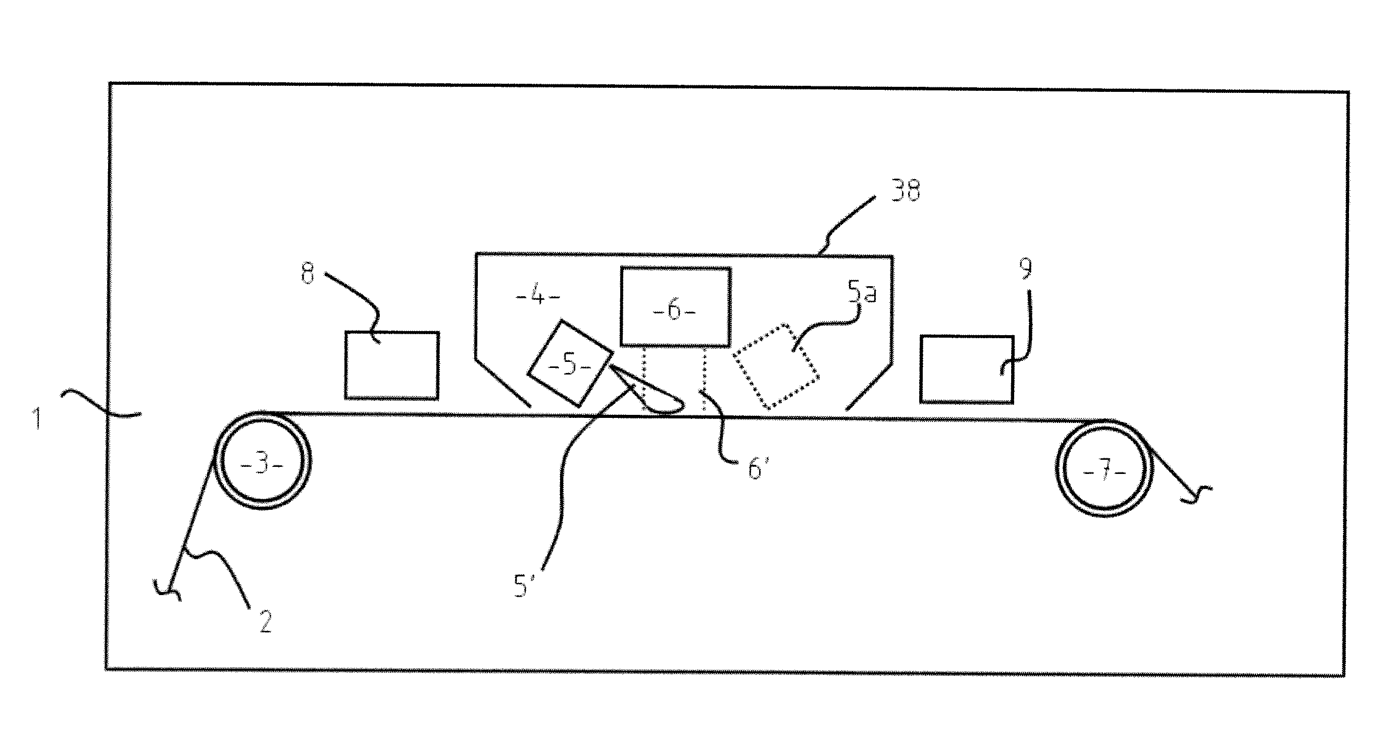
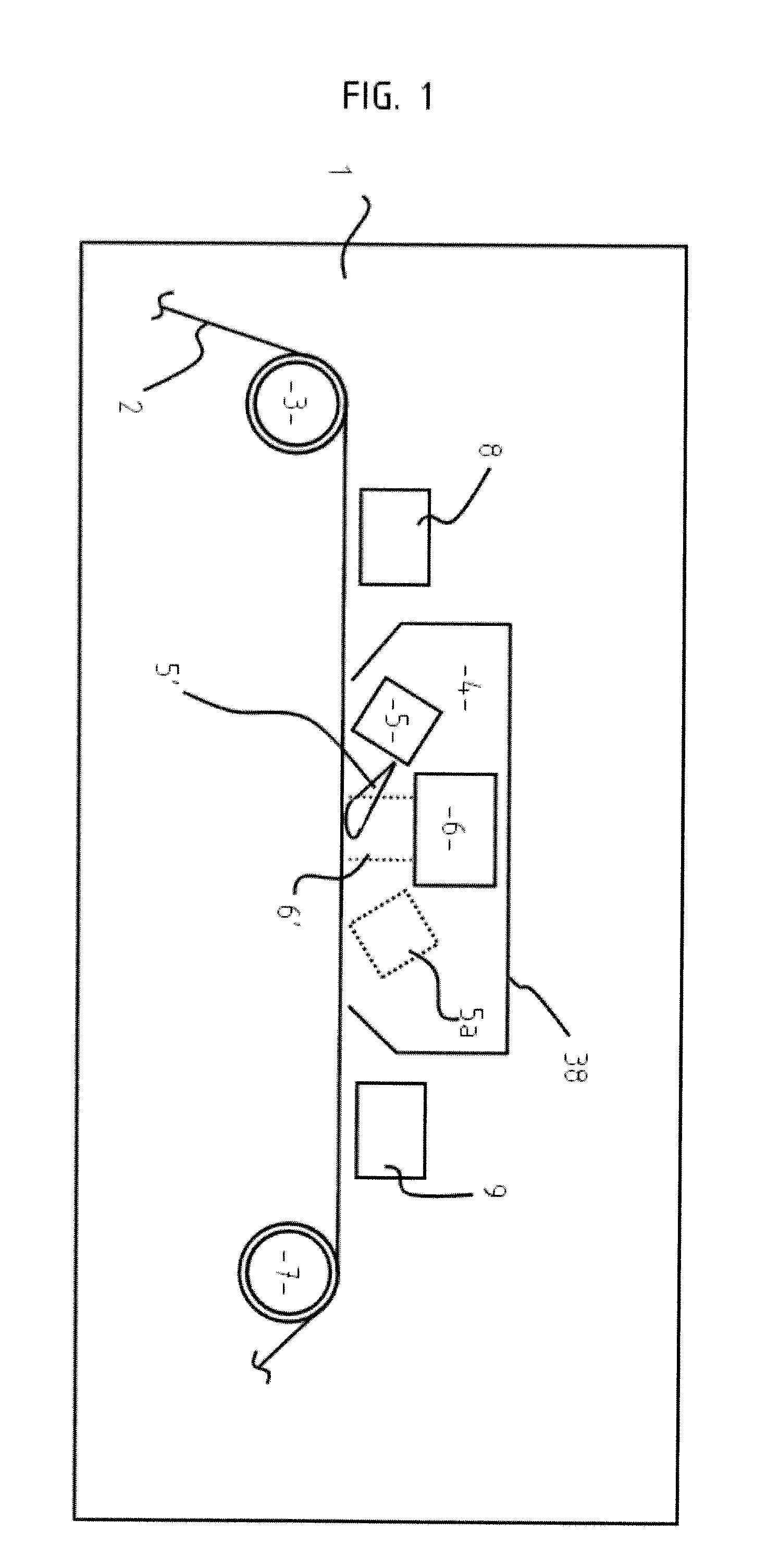
[0055]In this example, a planar magnetron low pressure plasma source was used for curing comprising an Edwards 75 mm planar magnetron and MDX DC power supply; in the treatment space, an acrylate delivery source was located between the plasma source and the substrate, and the delivery was directed away from the plasma source towards the substrate. The acrylate used was tripropylene glycol diacrylate TRPGDA. The substrate was static for deposition and curing. A single hole heated precursor delivery pipe was placed in-front of the source facing toward the substrate, as in the manner of FIGS. 5a, 5b. The pipe was heated using a variable heating supply 200 watts at 240 volt (mark space modulation, 10% duty cycle) for 8 minutes. The cathode was run in constant current mode at a current of 200 mA using residual ambient air at 6×10⁻² mbar. 8 ml of material was delivered in 3 seconds and the resulting substrates were coated with cured acrylate that had excellent adhesion.

example 2

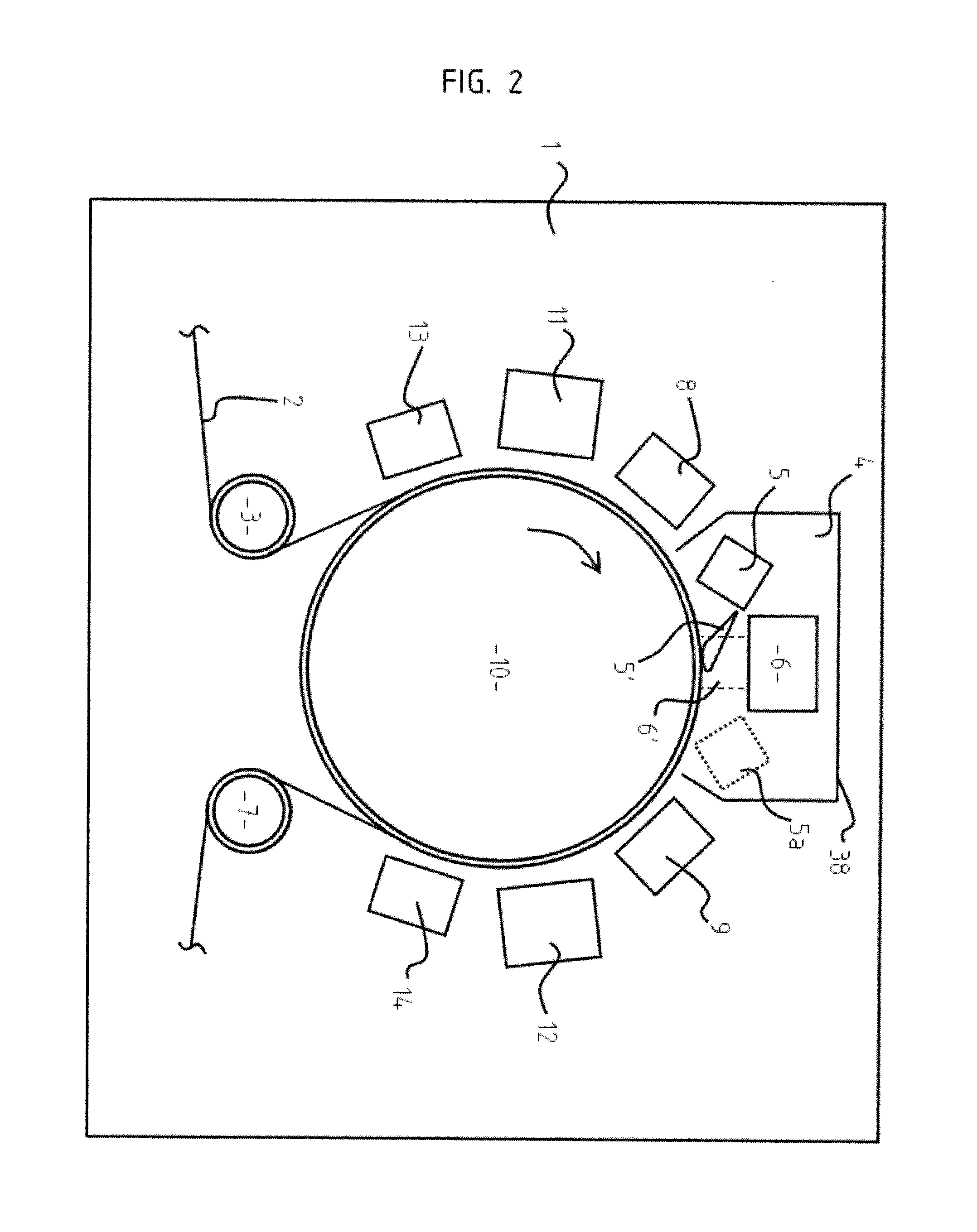
[0056]In this example, two dual planar magnetrons were used with plasma delivery between them in the manner of FIG. 6. Power was supplied by a DC magnetron power supply unit. The PID controlled heated pipe had internal baffles, and the precursor TRPGDA was delivered to the pipe on the opposite side to the moving web. A 30 mm slot machined in the pipe facing the moving web provides the output precursor beam. With DC powers in excess of 200 watts on the two 2 inch diameter cathodes, these were arranged 60 mm above the 150 mm coating drum that carries the moving web. At pressures of 2×10⁻² mbar of argon and the 20 mm diameter heated delivery pipe fitted within the 25 mm space between the cathodes and, with the 20 mm slot positioned 50 mm from the web, 0.2 ml of precursor was delivered in 1.5 minutes through the 20 mm slot aligned to intersect with a substantial proportion of the electron flux from the two cathodes at the substrate surface. The substrate was coated at 30 meters per minu...

example 3

[0057]In this example, the apparatus of FIGS. 5a and 5b was used. The plasma source is a 4 inch sputter cathode with very weak magnetic field and a 6 inch (oversize) reaction plate. The precursor source comprised a heated precursor delivery pipe (¾ inch diameter) with 4 mm exit aperture in-front of the 6 inch cathode surface, centrally mounted with exit aperture facing the web 20 mm below cathode, 30 mm from the web surface and using oxygen / nitrogen atmosphere at 3×10⁻¹ mbar. The cathode was run at 150 watts and the pipe heated to 260 degrees C. with the delivery of liquid acrylate 4 inches away from the 4 mm pipe exit and 180 degrees opposite the exit aperture. The acrylate was delivered through a needle metering valve and the resulting coating was well cured acrylate deposition with excellent adhesion and good uniformity in the machine and transverse directions.


PUM

PropertyMeasurementUnit
Massaaaaaaaaaa
Energyaaaaaaaaaa
Energyaaaaaaaaaa

Abstract

A process for coating a substrate comprising condensing a radiation curable material on a substrate and curing it using an electron flux 6′ with energy between 6.5 eV and 300 eV. The electron flux 6′ is directed at the substrate (2) either simultaneously or sequentially with delivery of the curable material (5′). Curing is preferably initiated spatially and temporally concurrently with delivery of the material to the substrate. The electron flux is preferably generated using a low pressure gas plasma source with a driving voltage negative relative to the local voltage conditions. The low pressure gas plasma (6′) is preferably magnetically enhanced and, for example, incorporates a magnetron.

Description

TECHNICAL FIELD[0001]This invention relates to coated substrates and apparatus and processes for coating substrates.[0002]Films having enhanced barrier properties for oxygen or other gases or odours or water vapour are produced by depositing alternate layers of cured polymer and metal or compounds onto a web substrate using processes such as vacuum deposition. These films are useful for packaging of oxygen or moisture sensitive foodstuffs, encapsulation of gas or moisture sensitive components, and a variety of other functional applications requiring barrier properties. Films are also manufactured having an enhanced holographic effect, isotropic light scattering or colour shift by depositing alternate layers of a transparent or translucent cured polymer and a metal onto a web substrate.[0003]It is known to deposit layers of cured polymer onto a web substrate using vacuum deposition. However, the existing sequential processes of vacuum condensation and curing of polymer precursors hav...

Claims


Application Information

Patent Timeline
IPC IPC(8): C08J7/18
CPCB05D1/60B05D1/62B05D3/068B05D3/147H01J2237/316B05D2252/02B05D2350/60H01J37/077B05D7/04
Inventor TOPPING, JOHNANTHONY, DAVID
Owner CAMVAC
Why Eureka
Try Eureka