Simplified three-stage fuel processor

Active Publication Date: 2005-08-23
GAS TECH INST
View PDF1 Cites 26 Cited by
  • Summary
  • Abstract
  • Description
  • Claims
  • Application Information

AI Technical Summary

Benefits of technology

[0003]Accordingly, it is one object of this invention to provide an inexpensive apparatus and method for removing or substantially reducing the quantity of carbon monoxide in a mixture of hydrogen, carbon dioxide and carbon monoxide resulting from the reforming of hydrocarbon fuels.
[0004]It is another object of this invention to provide an apparatus and method for reforming hydrocarbon fuels which renders the fuels usable in applications such as fuel cells without additional processing subsequent to reforming.
[0006]These and other objects of this invention are addressed by a fuel processor structure comprising concentric reformer, shift and methanation reactor vessels in which reformer heating is provided by a natural gas combustor comprising a bed of combustion catalyst and a ceramic start-up burner plate and in which steam for the reformer is generated in coiled vaporizer tubes heated by convection and from infrared-radiation surfaces from the hot combustor flue gases. The reformer hydrocarbon fuel feed is down-flow through the reformer and countercurrent to the heating source provided by a combustion process producing a high temperature flue gas flow. The reformer bed preferably comprises alternating layers of larger and smaller catalyst particles to enhance reformer process gas mixing. In addition, the shift and methanation catalysts are combined into a single reactor vessel, thereby simplifying heat management and fabrication.
[0007]Tubing coils wrapped around the combustion zone between the combustion zone and shift / methanation vessel moderate product gas temperatures. Incoming process gas and water remove heat from the reformer process gas stream leaving the reformer vessel. The length of this coil and the amount of water determine the amount of cooling. Process water passing through the shift / methanation coils adsorbs heat from the combustion chamber and the process gas. This heat results in the incoming water producing hot water or saturated steam prior to entering the steam coil in the combustion chamber. This effect moderates temperatures vertically throughout the length of the shift / methanation catalyst bed and reduces the amount of backpressure required to process fuel. Pressure created during the water vaporization step required for the steam reforming process does not affect incoming reformer fuel. Hence, fuel pressure is maintained at a minimum, thereby saving the costs associated with pressurizing the incoming fuel to feed gas with incoming water.
[0009]Additional elements of this invention include the use of counter-current gas flow patterns for the reformer process gas stream and combustion flue gas stream so as to maximize fuel conversion and, thus, increase efficiency. In addition, the reformer / combustion / shift / methanation coils work together balancing heat flow by gas flows and catalysts temperature requirements to function optimally. Finally, insulation provides structural integrity to the fuel processor. The insulation binds the fuel processing vessel components and tubing into a single integrated compact structure.

Problems solved by technology

Although the shift reaction substantially reduces the carbon monoxide present in the effluent, it is still too high for use in fuel cells such as polymer electrolyte membrane (PEM) fuel cells.
However, for several reasons, this method is less than ideal.
Firstly, the catalysts employed by such schemes are not 100% carbon monoxide selective.
Secondly, significant combustion heat is evolved from consuming both carbon monoxide and hydrogen gases, thereby requiring the use of two or three stages coupled with heat exchanger equipment and controls for metering air bleeding.
Thirdly, the air has to be metered in proportion to the amount and duration of the carbon monoxide content.
And, fourthly, these systems are expensive to build and there is at present no accurate, real-time carbon monoxide sensor suitable for use in this system, as a result of which, in transient states, excess hydrogen is combusted to assure all of the carbon monoxide is consumed.

Method used


Image

  • Simplified three-stage fuel processor
  • Simplified three-stage fuel processor
  • Simplified three-stage fuel processor

Examples


Embodiment Construction

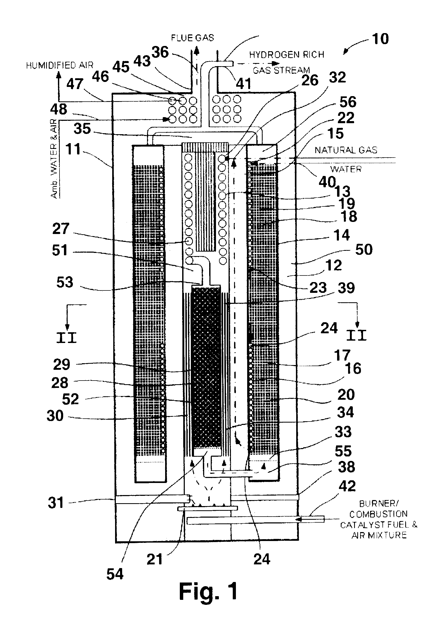
[0015]The fuel processor of this invention is suitable for converting hydrocarbon-containing gaseous and liquid fuels, such as natural gas, naphtha and alcohols, to a hydrogen-rich synthesis gas. Such hydrogen-rich synthesis gas is suitable for use in fuel cells, such as PEM fuel cells, without additional processing for removal of carbon monoxide as is frequently required of synthesis gases produced in a conventional manner. The fuel processor can also be used, as previously indicated, to supply hydrogen for a hydrogen refueling station.

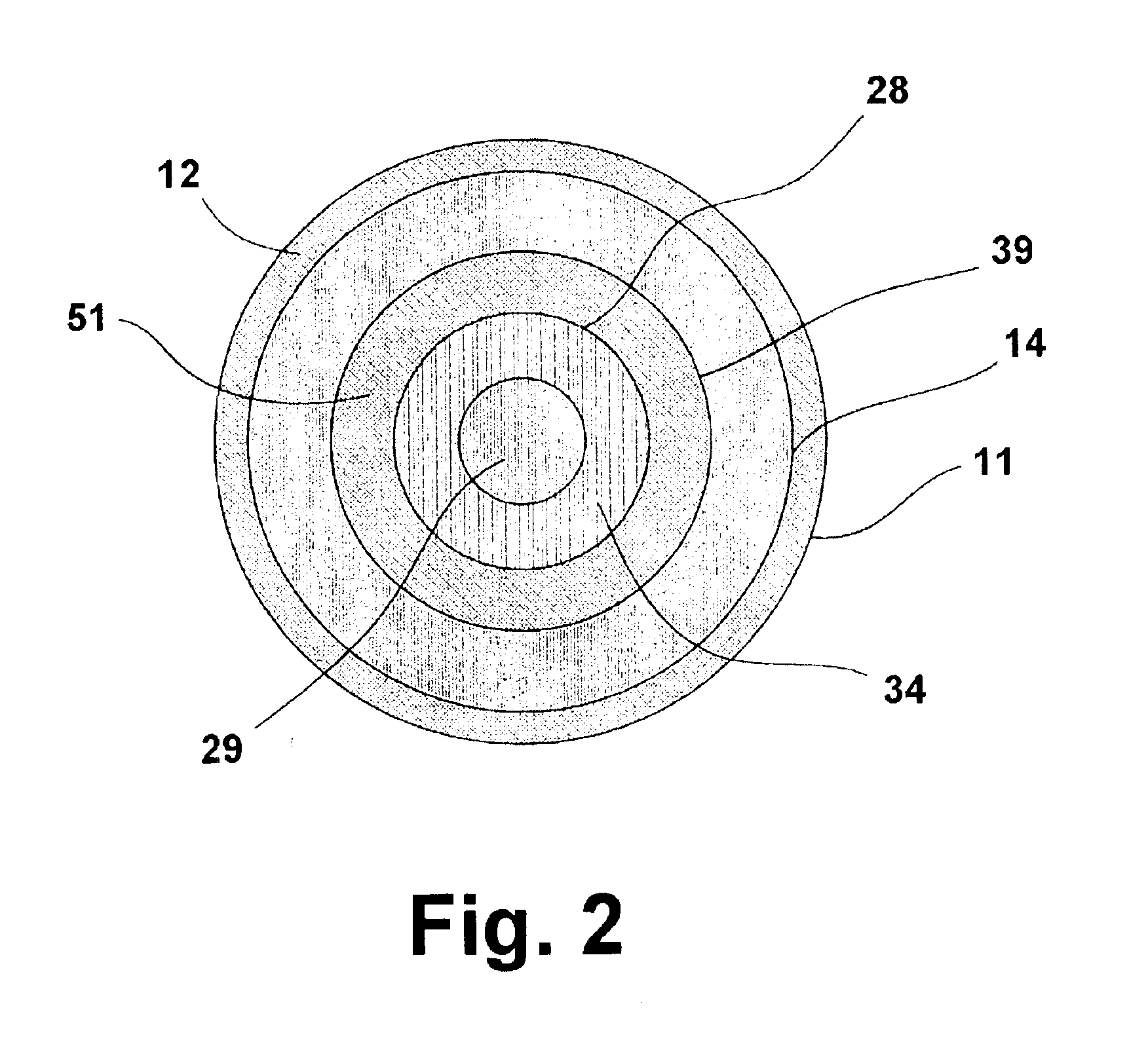
[0016]The fuel processor of this invention is comprised generally of a housing, partially filled with an insulating material which is used to contain and insulate the various components of the processor as discussed in more detail herein below. The fuel processor of this invention comprises four basic sections, a heat exchange section comprising a methanator cooling coil, a steam coil and a shift cooling coil, a hydrocarbon reformer section comprisin...


PUM

PropertyMeasurementUnit
Temperatureaaaaaaaaaa

Abstract

A fuel processor for producing a hydrogen-rich product gas suitable for direct use in fuel cell applications includes a housing, an annular shift / methanator reactor vessel at least one reactor vessel wall disposed within the housing and forming an outer annular space between the at least one reactor vessel wall and the housing. A combustion chamber having at least one combustion chamber wall and forming a first inner annular space between the at least one combustion chamber wall and the at least one reactor vessel wall is disposed in the interior space formed by the annular shift / methanator reactor vessel, and a reformer reactor vessel having at least one reformer vessel wall and forming a second inner annular space between the at least one reformer vessel wall and the at least one combustion chamber wall is disposed within the combustion chamber.

Description

BACKGROUND OF THE INVENTION[0001]This invention relates to a fuel processor and method for reforming natural gas and other hydrocarbon fuels to produce a reformed fuel suitable for direct use in an electrochemical fuel cell. More particularly, this invention relates to a fuel processor and method whereby natural gas or other hydrocarbon fuels are first subjected to the well-known reforming reactions in which the fuel is reacted with steam, resulting in the formation of a reformer effluent comprising hydrogen, carbon dioxide and a substantial amount of carbon monoxide. To reduce the amount of carbon monoxide, the reformer effluent is subjected to a shift reaction in which the carbon monoxide reacts with steam to provide carbon dioxide and additional hydrogen. Although the shift reaction substantially reduces the carbon monoxide present in the effluent, it is still too high for use in fuel cells such as polymer electrolyte membrane (PEM) fuel cells. Subsequent methanation in accordanc...

Claims


Application Information

Patent Timeline
IPC IPC(8): C01B3/00C01B3/48C01B3/38C01B3/58B01J8/04H01M8/06
CPCB01J8/0449B01J8/0465B01J8/0496C01B3/384C01B3/48C01B3/586B01J2208/00141B01J2208/00203B01J2208/00309B01J2208/00504B01J2208/00513B01J2208/0053B01J2208/00548B01J2208/00716C01B2203/00C01B2203/0233C01B2203/0283C01B2203/0445C01B2203/047C01B2203/066C01B2203/0811C01B2203/0883C01B2203/1241C01B2203/127C01B2203/1288C01B2203/1604C01B2203/82H01M8/04126H01M8/0631H01M8/0668Y02E60/50
Inventor WANGEROW, JAMES R.MEADOWS, ALVIE R.HILL, ANDY H.ONISCHAK, MICHAEL
Owner GAS TECH INST
Why Eureka
Try Eureka