
Network-based system for the manufacture of parts with a virtual collaborative environment for design, development and fabricator selection

a network-based system and collaborative environment technology, applied in the field of network-based system for the manufacture of parts with a virtual collaborative environment for design, development and fabricator selection, can solve the problems of complex engineering effort involving multiple disciplines, long and costly process, and conventional approach to engineering design and development effort, so as to reduce the need for specialized software and hardware capabilities, reduce the processing burden of user stations, and reduce the effect of transaction costs

Inactive Publication Date: 2005-08-09
CHEMTRON RES
View PDF20 Cites 124 Cited by
  • Summary
  • Abstract
  • Description
  • Claims
  • Application Information

AI Technical Summary

Benefits of technology

[0018]It is another object of the present invention to provide such a network-based system whereby a central server maintains engineering data, such as design documents and three dimensional model data, in a common, neutral format, which is accessible by authorized team members through a graphical user interface that is substantially platform independent to reduce or eliminate the necessity for specialized hardware and software.
[0023]It is another object of the present invention to provide an electronic marketplace and bidding system whereby a prime contractor can solicit proposals or bids in a virtual environment including the provision of specification and three-dimensional model data to prospective fabricators for consideration in developing their proposals.
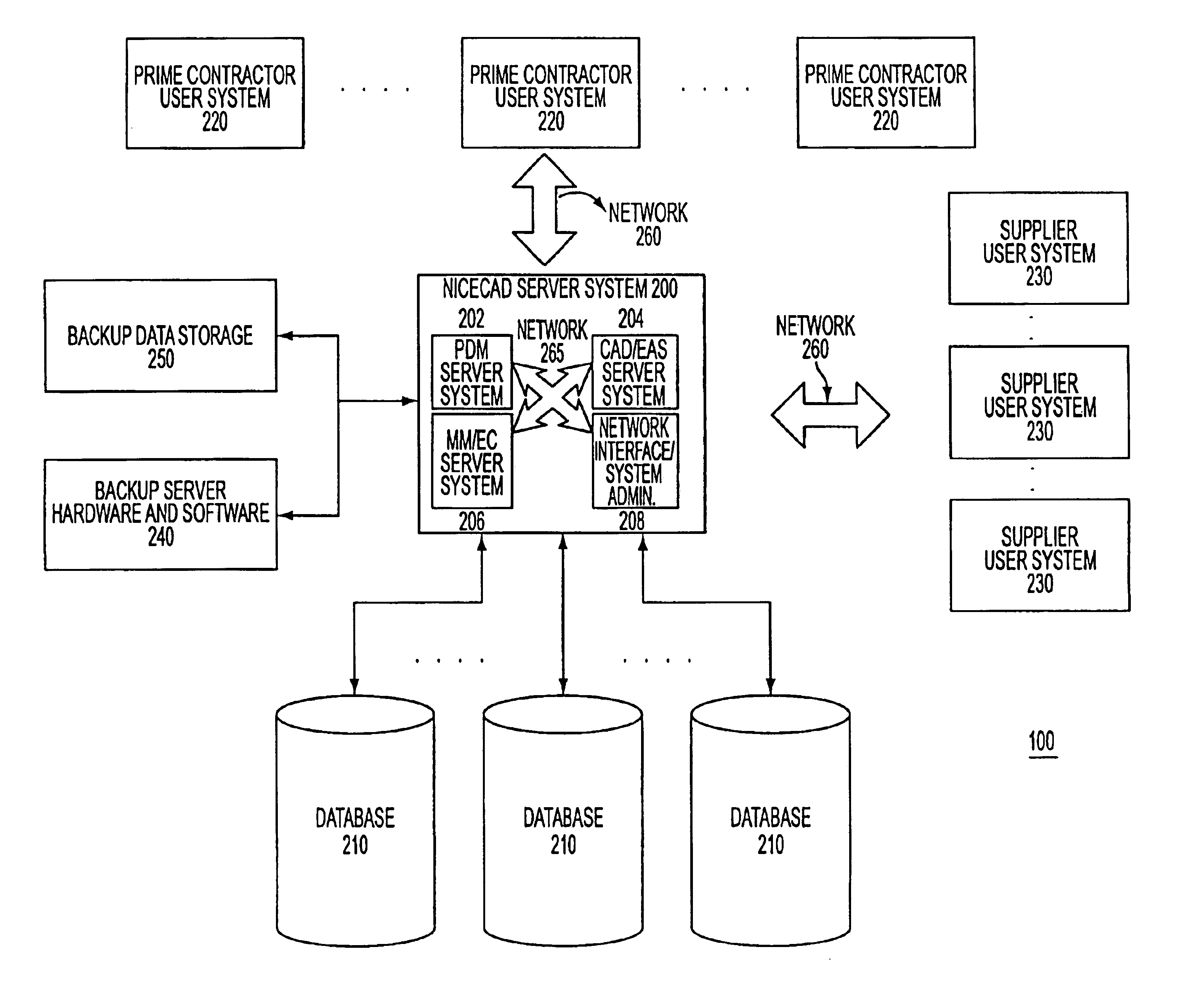
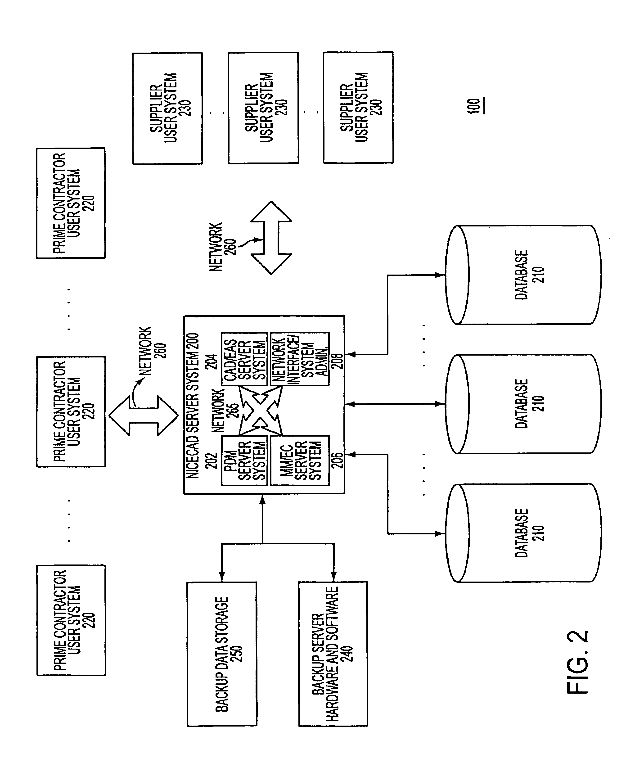
[0026]Accordingly, what is disclosed is a network-based system interfacing multiple user systems which interface through a central server to undertake the design development effort. A baseline design is created and maintained in a neutral or common format by the central server. A governing entity or prime contractor assigns access or authorization data so that parts or the entirety of the three dimensional model and / or specification data is accessible by other team members in order to perform various analysis and simulations. An integrated product data management (PDM) capability manages access to controlled data and maintains a record of the various manifestations of the design. A current baseline design is maintained so that engineering analysis and simulation team members perform their analysis on the correct design. The system supports quasi-real-time interactive audio, video and graphics so that team members can discuss design issues in the virtual environment without having to cross geographic or format boundaries. The above-described capabilities are provided in a substantially platform independent manner using a graphical user interface (GUI) supported by standard software, such as a “browser,” which may further include machine independent applications, such as Java Applets™, or, for certain required tools, a semi-machine-dependent application, to reduce the processing burden on user stations and the need for specialized client-side software. In an alternative embodiment of the invention, a so-called “custom browser” may be provided to user stations so that the interface with the central server system is tailored to the present application. In yet another embodiment, certain graphics-intensive applications may be provided by the central server as client-side applications to be compiled and executed, such as applications coded in Open GL™ by Silicon Graphics™. The so-called common denominator in these embodiments is the goal of retaining the most calculation intensive tasks on the server side of the overall system so as to reduce the need for specialized software and hardware capabilities at the user systems. Additionally, by receiving, converting, and maintaining part design models in a common, neutral format, the central server system provides the important benefit of “data neutrality” for the participants in a concurrent engineering development project. In short, format boundaries are obviated. This is an important benefit, especially for small enterprises, which might otherwise be eliminated from participation in a project because their software resource do not support a format required by a prime contractor.
[0027]A second aspect of the system provides a database of fabricators, a so-called “Global Manufacturer's Registry,” which can be searched by a designer or prime contractor to identify qualified fabricators. The database contains various information describing the fabricators, such as location, experience, machinery and process capabilities, certifications, quality assurance / inspection standards, and so forth. Fabricators are incentivized to enroll in the registry because it provides an incidental benefit as a capability management system they can use to manage and track their resources and capabilities. A prime contractor with a part design model representing a product can conduct a search to identify qualified fabricators based on design-specific and general criteria. The system includes producibility logic to analyze an uploaded part design in order to help identify qualified fabricators. The system allows prime contractors to provide feedback on performance which can be factored into a quality assurance capability provided by the system. As with the NICECAD aspect of the integrated system, the GMR aspect provides data neutrality for users by supporting the upload and conversion of part design models from various format types into a standard neutral format. Therefore, a designer is not precluded from using the GMR system based on the fact that it uses a particular part design model format.
[0028]According to a third aspect of the system, an electronic bidding system is provided by an Electronic Trading Community (ETC) to allow virtual discussions and negotiations to take place over the networked system once a pool of qualified fabricators is identified. A request for quote (RFQ) or request for proposal (RFP) with design data is submitted to the system so that fabricators can submit proposals. The virtual computer aided design (CAD) capability allows quasi-real-time discussions, including audio, video and graphics. The graphics capability allows a prime contractor and prospective fabricator to view the three-dimensional part design, including the execution of various manipulations, such as virtual rotations and translations, pan, zoom and “fly throughs.” The stored part design model data may include links to associated specifications, standards and other design specific documents so that the bidding fabricator has a full representation of what it is bidding on. As with the NICECAD and GMR aspects of the integrated system, the ETC provides “data neutrality” so that format boundaries do not become impediments for either the soliciting prime contractor / designer or the bidding fabricator.
[0029]In general, the above capabilities are provided in a networked, virtual environment that reduces transaction costs and meets engineering challenges as it transcends geographic, business and format boundaries. One or more central servers maintain the part design model in neutral format, such as AP 214 STEP format, well known to those of skill in the art. Substantially platform user independent graphical interfaces, such as browser pages, and server-client interactive applications, such as Java Applets™ make the system substantially user-system independent. In some instances, instead of using Java™ mini-applications or the like to run on a browser's so-called “virtual machine,” certain graphics-intensive or computation-intensive applications may be compiled and executed at the user systems as semi-machine-dependent applications amenable to operations using a computer system with a standard operating system. Whether specialized applications are supported by miniapplications (e.g., such as those coded in Java™) provided through a browser or by server interface with a semi-machine-dependent application at a user station (e.g., a server-provided application coded in Open GL™ readily executed on a Unix™- or Windows™-based system), the goal is a substantial user platform independent network interface with the server system. Security is provided through encryption and multiple firewalls at the server(s) so as to protect proprietary and sensitive data.

Problems solved by technology

The conventional approach to an engineering design and development effort tends to be costly and cumbersome.
Because a number of disciplines may be involved, it can be appreciated that the process can be lengthy and costly.
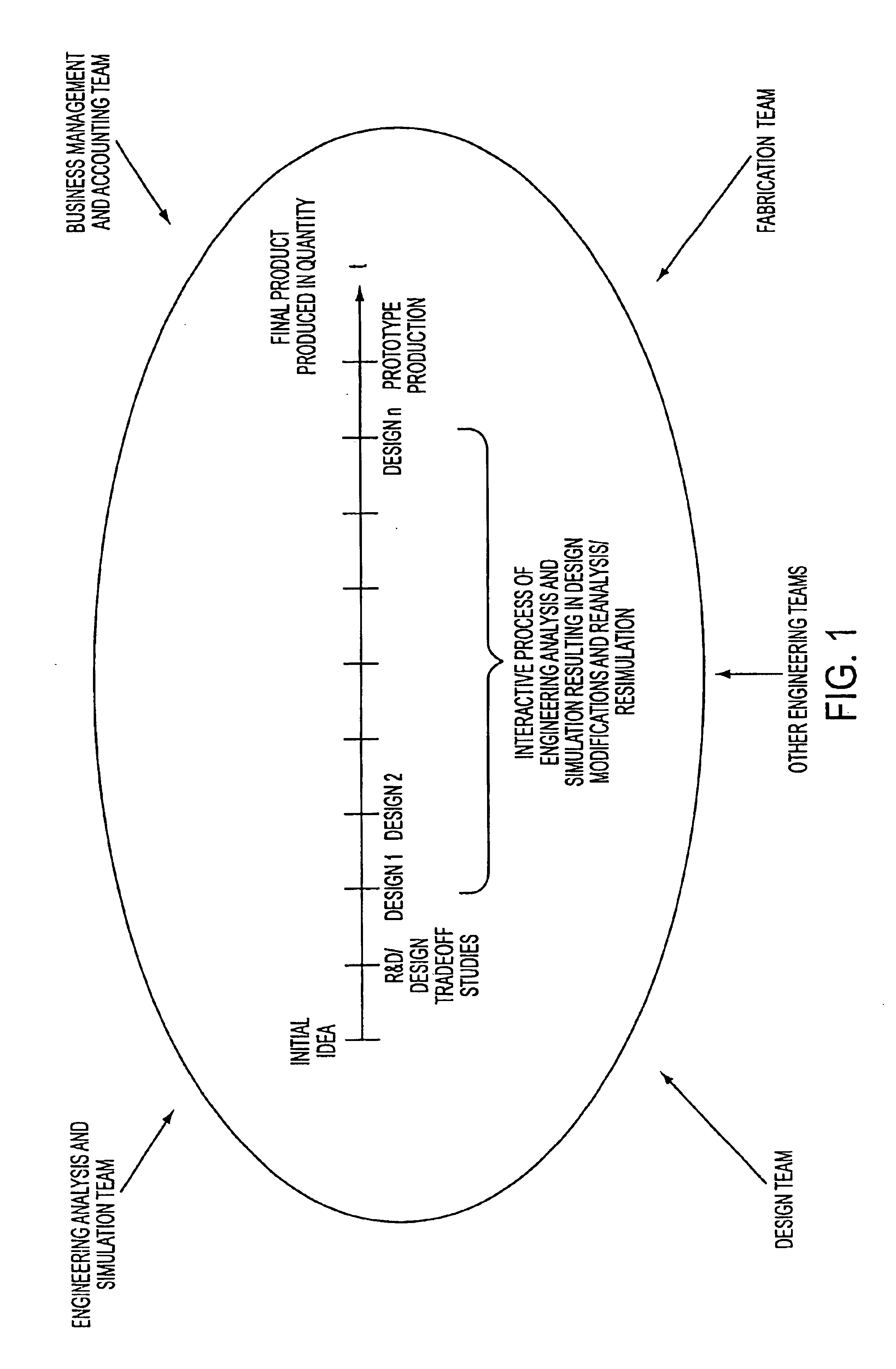
Nevertheless, the sonobuoy example and FIG. 1 illustrate how a complex engineering effort involving multiple disciplines can be a lengthy and costly process as designs are considered and discarded, new designs are evaluated and so forth.
When the various specialists are in different geographical locations (“physical boundaries”), at different business entities (“business boundaries”), or employ different software standards (“format boundaries”), the problem is only compounded.
This can be referred to as the “boundaries problem.” Put simply, having specialists of differing disciplines (with often conflicting priorities) attempt to resolve design issues when operating from different locations, or from business entities with differing business practices and cultures, or when using different software formats (e.g., three dimensional model standards) creates significant costs and obstacles.
This is a significant drawback.
The engineering concern may not have established relationships with many—or any—manufacturers.
Of the few potential candidates that may be identified through “word of mouth” or a costly search, it can be costly to evaluate whether such candidates meet minimum requirements.
Even then, it may be difficult to ascertain the quality of past performance and the prospects for the proposed performance.
The engineering concern will have to sustain the cost, and risk, of divulging proprietary design and specification data.
Because format standards may differ, the costs and risks of (sometimes imperfect) file conversions may be required.
These are significant drawbacks.
This lessens competition and ultimately, can lead to increased costs and decreased performance.
These are significant disadvantages to the engineering concern.
With respect to start-up or not-well-known fabricators, this is a significant drawback that prevents them from penetrating new markets and inhibits their growth.
Despite rigorous concurrent engineering, it is common that minor and not-so-minor redesigns may be required due to producibility concerns.
The time and effort entailed are significant drawbacks.
Engineering issues aside, the negotiation process can be lengthy and costly.
Typically conducted using a combination of the phone, teleconference and postal service (or the like), these discussions impose additional costs and time in getting a product to market.
This is a significant drawback.
Other problems and drawbacks also exist.

Method used


Image

  • Network-based system for the manufacture of parts with a virtual collaborative environment for design, development and fabricator selection
  • Network-based system for the manufacture of parts with a virtual collaborative environment for design, development and fabricator selection
  • Network-based system for the manufacture of parts with a virtual collaborative environment for design, development and fabricator selection

Examples


Embodiment Construction

[0061]As discussed in the Summary of the Invention, the present invention is directed to providing a networked, virtual, collaborative environment for three aspects of an engineering development: (1) the design and development phase (referred to as the NICECAD or Network Integrated Concurrent Engineering Computer Aided Design); (2) the identification and evaluation of qualified fabricators or manufacturers for a design (referred to as the Global Manufacturer's Registry or GMR system or the Interactive System for Engineering Design and Manufacture (EDM), and (3) the solicitation and evaluation of requests for proposals or quotes from qualified bidders (referred to as the Electronic Trading Community or ETC).

The First Aspect of the Invention: A System and Methods for Undertaking an Engineering Design and Development Effort in a Virtual and Collaborative Environment

[0062]In general, the NICECAD server system provides Product Data Management (PDM), CAD functionality, engineering analysi...


PUM


Abstract

The invention relates generally to a comprehensive, integrated computer-based system and method for undertaking an engineering design and development effort in a virtual collaborative environment, identifying qualified fabricators for manufacturing a part design based on fabricator capability information stored in a global registry database substantially maintained by the fabricators themselves, and conducting a virtual bidding process whereby electronic representations of three dimensional model and specification data are provided by a central server. The central server further supports the bidding process by providing quasi-real time audio, video and graphics, and the contracts negotiation and formalization steps.

Description

RELATED APPLICATIONS[0001]This application is a continuation of U.S. application Ser. No. 09 / 410,619, filed Oct. 1, 1999, now U.S. Pat. No. 6,295,513, which is a continuation-in-part of U.S. application Ser. No. 09 / 270,007, filed Mar. 16, 1999, entitled “Interactive System for Engineering Design and Manufacture,” now abandoned, U.S. application Ser. No. 09 / 311,150, filed May 13, 1999, entitled “Network Integrated Concurrent Engineering With Computer Aided Design,” now abandoned, both of which are herein incorporated by reference.FIELD OF THE INVENTION[0002]The present invention relates generally to a comprehensive, integrated computer-based system and method for undertaking an engineering design and development effort in a virtual collaborative environment, identifying qualified fabricators for manufacturing a part design based on fabricator capability information stored in a global registry database substantially maintained by the fabricators themselves, and conducting a virtual bi...

Claims


Application Information

Patent Timeline
IPC IPC(8): G05B19/4097G05B19/4099G06F17/50G06Q30/00G06Q30/06
CPCG05B19/4099G06F17/50G06Q30/06G05B2219/32038G05B2219/32126G05B2219/35008G06F2217/04Y10S707/99945Y10S707/99948G06F2111/02G06F30/00Y02P90/02
Inventor THACKSTON, JAMES D.
Owner CHEMTRON RES
Learn More