Exposure apparatus and exposure method capable of controlling illumination distribution

Inactive Publication Date: 2005-08-09
NIKON CORP
View PDF33 Cites 76 Cited by
  • Summary
  • Abstract
  • Description
  • Claims
  • Application Information

AI Technical Summary

Benefits of technology

[0031]In this arrangement, an example of the predetermined illumination characteristic of the evaluation object is at least one of uneven illuminance of the exposure light beam and a collapse amount of a telecentric property (telecentricity) of the exposure light beam. Both of them are extremely important characteristics to obtain a high resolution on the second object. Further, it is desirable that the illumination characteristic of the evaluation objective includes an inclination component and a concave / convex component of the uneven illuminance of the exposure light beam, and inclination components (two-dimensional vector amounts) and a magnification component of the collapse amount of the telecentric property of the exposure light. The five components of the illumination characteristic can be easily controlled substantially singly by mutually independently driving a plurality of optical members in the illumination system. Therefore, it is especially easy to effect the automatization.
[0087]A method for producing a device according to the present invention comprises the step of transferring a device pattern onto a substrate by using the exposure method according to any one of the aspects of the present invention. According to the present invention, it is possible to mass-produce a highly functional device with a high line width control accuracy.

Problems solved by technology

However, when the operator performs the adjustment, an inconvenience arises such that a long period of time is required to perform the adjustment.
Therefore, there has been also such a fear that the adjustment time is further prolonged depending on the operator.
Therefore, the adjustment steps have been extremely complicated.
As described above, the adjustment for the conventional illumination optical system has required the complicated steps which take a long period of time.
Therefore, for example, it has been difficult to perform such an operation that the allowable level of a predetermined illumination characteristic is changed depending on, for example, the required accuracy for the device to be produced.
Further, for example, the uneven illuminance of the illumination characteristic is changed in a time-dependent manner, for example, due to the cloudiness of the optical member in the illumination optical system and the deterioration of the saltpeter material in some cases.
However, in such a case, it has been difficult for the conventional adjustment method to make quick response.
However, when the exposure apparatus is used for a long period of time, then a slight amount of remaining organic matter gradually increases the cloudiness of the lens, and the centro-symmetrical unevenness, in which the illuminance is lowered especially at the central portion, is sometimes advanced in a time-dependent manner.
However, when it is intended to correct the uneven illuminance by driving the lens having a certain curvature other than the flat plane, the uniformity of the coherence factor (σ value) of the illumination light beam is occasionally deteriorated in the illumination area on the reticle as the mask, and in the exposure area on the wafer as the substrate to be exposed.
When the uniformity of the σ value is deteriorated in the exposure area as described above, an inconvenience arises such that the line width uniformity, which is the original object of the suppression of the uneven illuminance, is lowered.
On the other hand, if the correction amount of the uneven illuminance is set so that the deterioration of the uniformity of the σ value is suppressed, a limit appears in the line width control accuracy.

Method used


Image

  • Exposure apparatus and exposure method capable of controlling illumination distribution
  • Exposure apparatus and exposure method capable of controlling illumination distribution
  • Exposure apparatus and exposure method capable of controlling illumination distribution

Examples


first embodiment

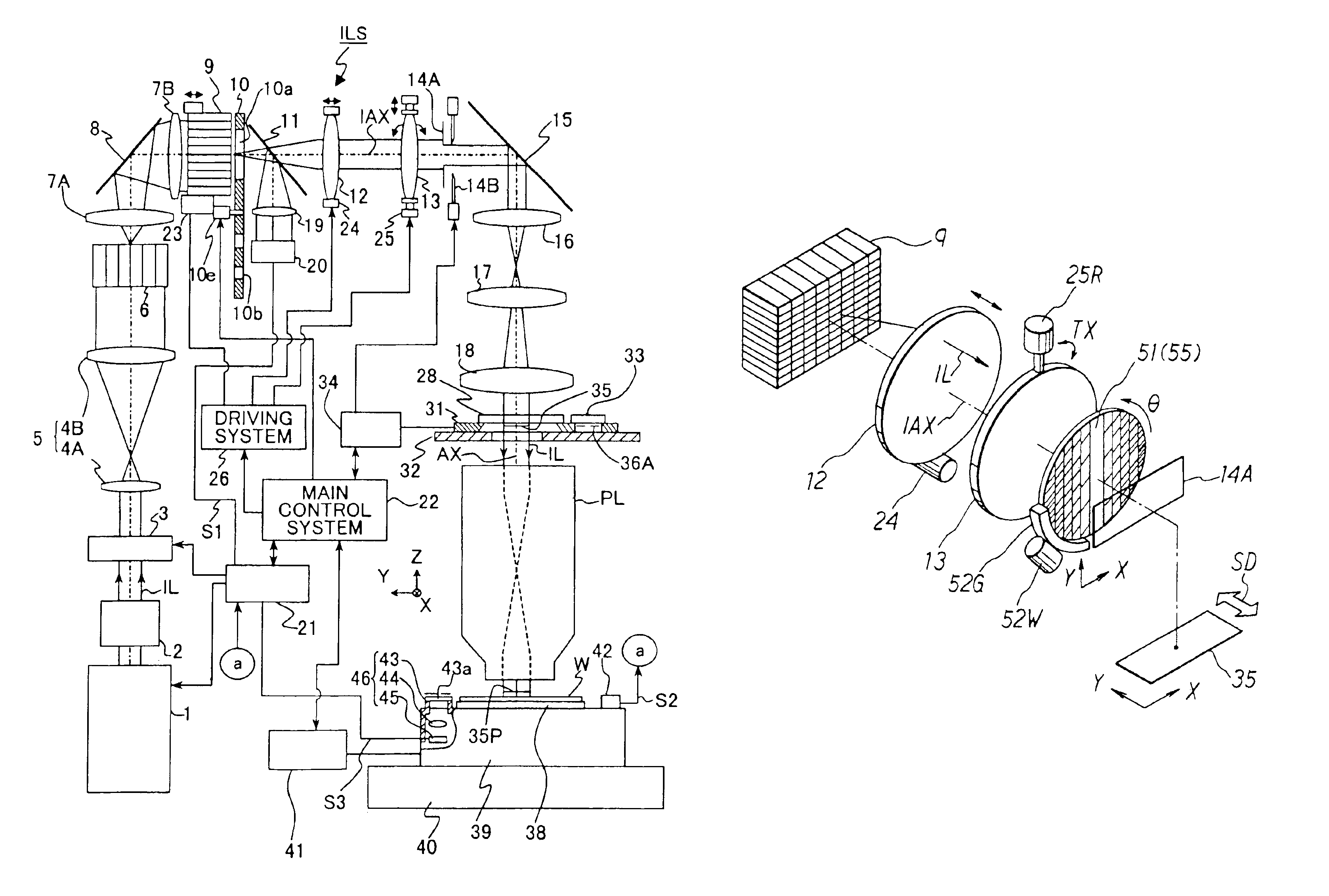
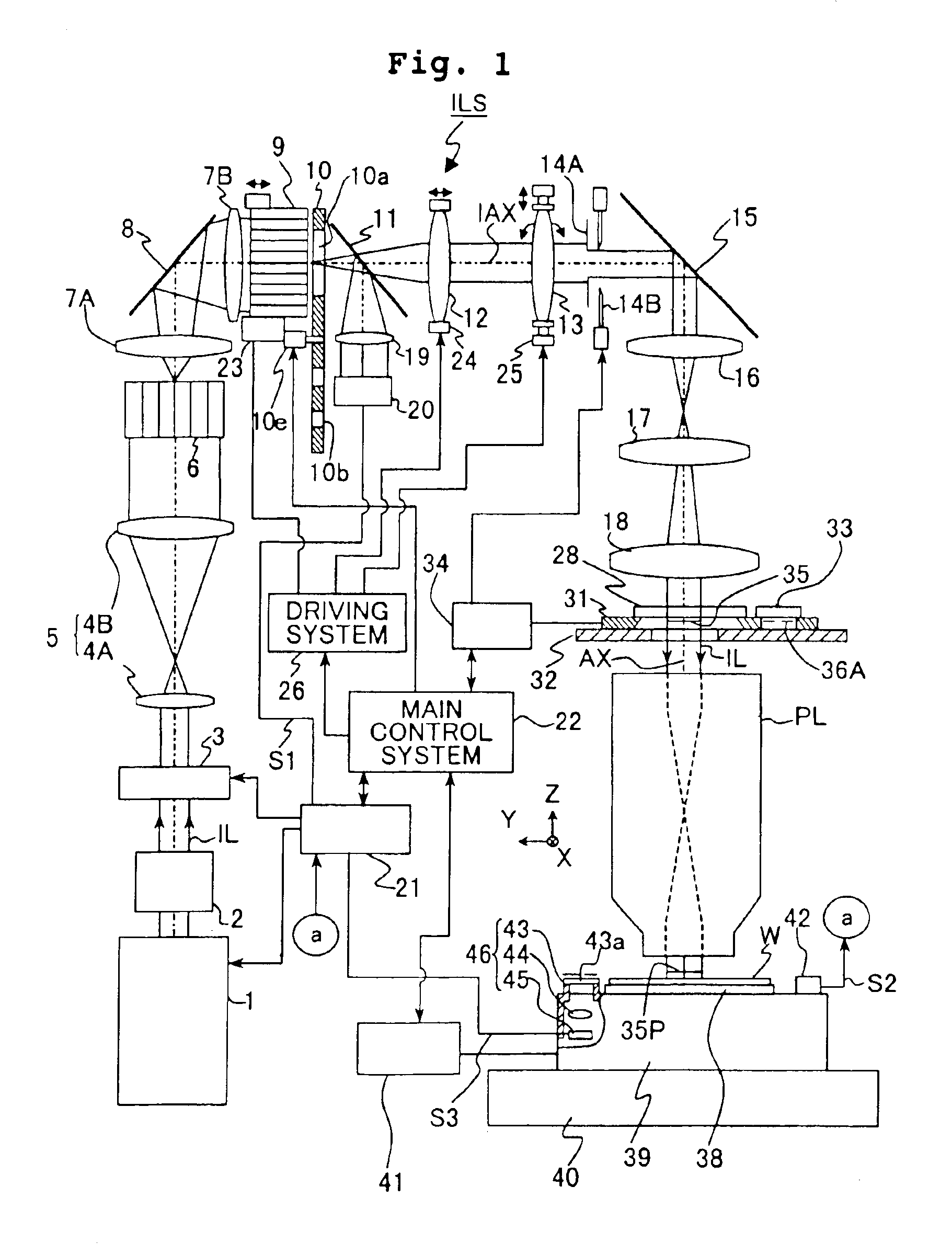
[0109]FIG. 1 shows a schematic arrangement of a projection exposure apparatus of this embodiment. In FIG. 1, an ArF excimer laser light source (wavelength: 193 nm) is used as an exposure light source 1. However, those usable as the exposure light source 1 include, for example, a KrF excimer laser (wavelength: 248 nm), an F2 laser (wavelength: 157 nm), a Kr2 laser (wavelength: 146 nm), a high harmonic wave generator of YAG laser, a high harmonic wave generator of semiconductor laser, and a mercury lamp. An exposure light beam IL (exposure beam), which is composed of an ultraviolet pulse light beam having a wavelength of 193 nm radiated from the exposure light source 1, passes through a beam matching unit (BMU) 2 for positionally matching the optical path with respect to the main exposure apparatus body, and it comes into a variable light-reducing unit 3 to serve as a light attenuator. An exposure control unit 21, which is provided to control the exposure amount with respect to the ph...

second embodiment

[0162]Next, explanation will be made for an example of the adjusting method adopted when the modified illumination is performed by installing the aperture diaphragm 10b for the zonal illumination (or the aperture diaphragm 10c for the four-spot illumination) at the light-outgoing plane of the second fly's eye lens 9 as shown in FIG. 6A with the illumination optical system of this embodiment.

[0163]In this case, the light amount distribution-converting element 55, which is composed of a diffractive optical element (DOE), is installed in place of the first fly's eye lens 6 shown in FIG. 1. In place of the diffractive optical element, a prism including, for example, a conical prism (axicon for zonal illumination) and a prism of the quadrangular pyramid type (pyramid type) (for four-spot illumination) may be used. In order to adjust the illumination area of the exposure light beam IL with respect to the second fly's eye lens 9 depending on whether the aperture diaphragm to be used is the...

third embodiment

[0177]This embodiment is illustrative of a case in which a filter (member) of the present invention is used. FIG. 11 shows a schematic arrangement of a scanning exposure type projection exposure apparatus based on the step-and-scan system of this embodiment. This exposure apparatus has substantially the same structure as that of the exposure apparatus according to the first embodiment except that a concentration filter plate 51 corresponding to a planer area with a variable transmittance distribution is provided, the driving system for the fly's eye lens 9 is not provided, and the structure of the driving system 25 is different from that in the first embodiment.

[0178]The concentration filter plate 51 is provided in the illumination optical system ISL. More specifically, the concentration filter plate 51 is arranged at the plane which is further defocused by a predetermined amount from the fixed blind 14A, i.e., at the plane which is slightly defocused from the conjugate plane with r...


PUM


Abstract

An exposure apparatus which expose a photosensitive layer on an object with light via a mask having a pattern to be transferred onto the photosensitive layer, includes an illumination optical system having plural optical elements provided along an optical axis substantially perpendicular to a plane on which the pattern is placed, and which include an optical integrator from which the mask is illuminated with the light through a part of the plural optical elements. The apparatus also includes a filter device having a rotatable filter element provided between the optical integrator and the plane, and having a transmittance distribution in a predetermined area. Light from the optical integrator passes through a portion in the predetermined area. Light from the filter element has a variable intensity distribution different from that of the light incident on the filter element from the optical integrator, and made variable by rotating the filter element.

Description

[0001]This is a Division of application Ser. No. 09 / 790,616 filed Feb. 23, 2001 now U.S. Pat. No. 6,771,350. The entire disclosure of the prior application is hereby incorporated by reference herein in its entirety.BACKGROUND OF THE INVENTION[0002]1. Field of the Invention[0003]The present invention relates to an exposure apparatus and an exposure method to be used in order to transfer a mask pattern onto a substrate through a projection optical system in the lithography step for producing, for example, semiconductor elements, liquid crystal displacement elements, plasma display elements, or thin film magnetic heads. In particular, the present invention relates to an exposure apparatus and an exposure method capable of controlling the distribution of illumination generated by an illumination system automatically or precisely.[0004]2. Description of the Related Art[0005]In order to respond to the improvement in the degree of integration and the degree of fineness of the semiconductor...

Claims


Application Information

Patent Timeline
IPC IPC(8): G03B27/42H01L21/027G03F7/20
CPCG03B27/42G03F7/70083G03F7/701G03F7/70191H01L21/027
Inventor NISHINAGA, HISASHI
Owner NIKON CORP
Why Eureka
Try Eureka