
Staged lean combustion for rapid start of a fuel processor

a fuel processor and lean technology, applied in the direction of sustainable manufacturing/processing, physical/chemical process catalysts, lighting and heating apparatus, etc., can solve the problem of increasing the potential for rwgs reaction, insufficient co oxidation, and excessive consumption of hsub>2 /sub>, so as to achieve rapid startup the effect of operating temperatur

Inactive Publication Date: 2005-08-09
GM GLOBAL TECH OPERATIONS LLC
View PDF17 Cites 26 Cited by
  • Summary
  • Abstract
  • Description
  • Claims
  • Application Information

AI Technical Summary

Benefits of technology

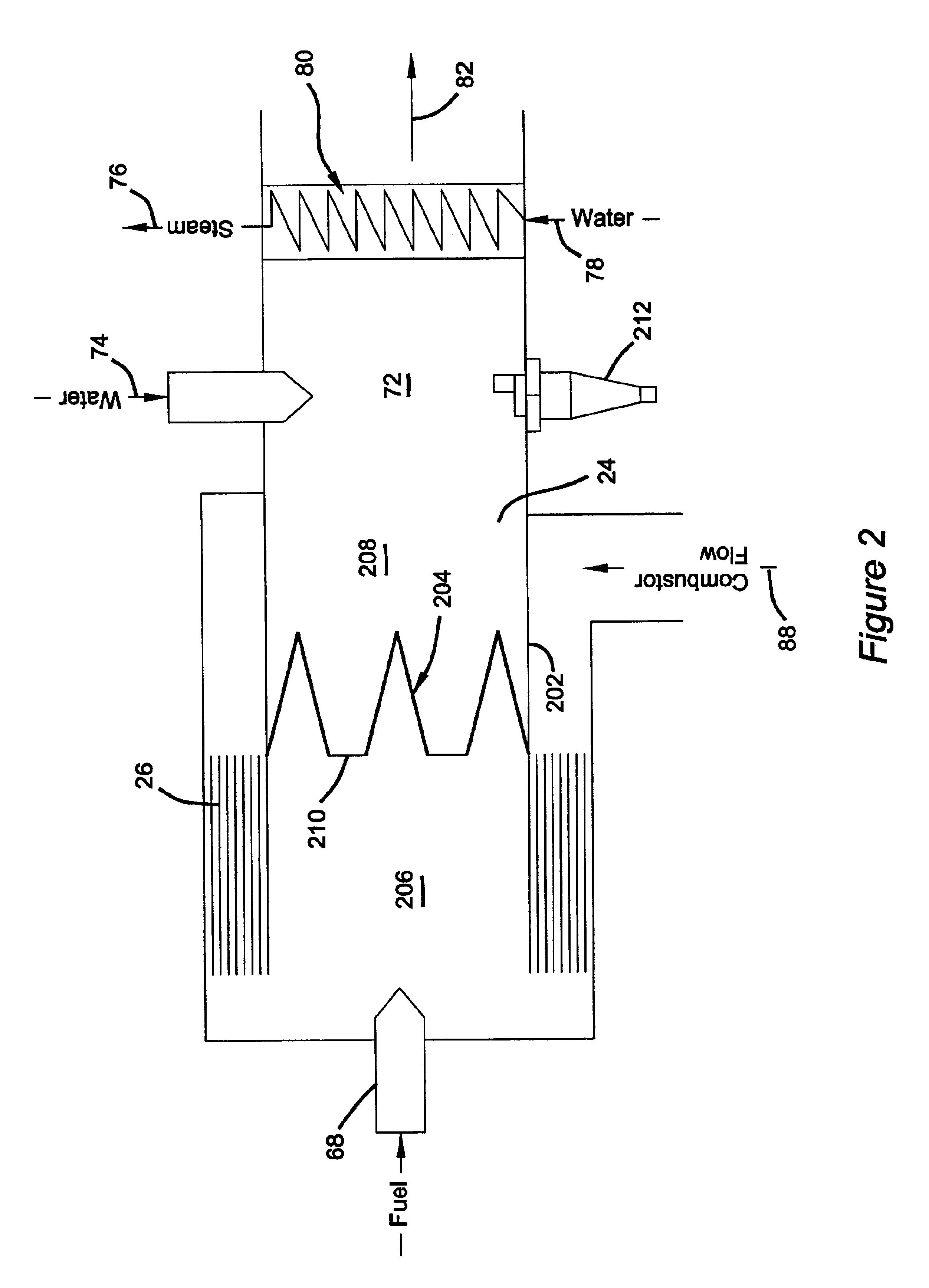
[0012]According to the principles of the present invention, a fuel processor for rapidly achieving operating temperature during startup is provided having an advantageous construction. The fuel processor includes a reformer, a shift reactor, and a preferential oxidation reactor for deriving hydrogen for use in creating electricity in a plurality of H2—O2 fuel cells. A first combustion heater system is coupled to at least one of the reformer, the shift reactor, and the preferential oxidation reactor to preheat the component(s) during a rapid startup sequence. That is, the first combustion heater system is operable to produce thermal energy as a product of the combustion of air and fuel in the form of a first heated exhaust stream. This first heated exhaust stream is then used to heat the component either directly or by using a heat exchanger type system.

Problems solved by technology

If the amount of O2 exceeds about two times the stoichiometric amount needed, excessive consumption of H2 results.
On the other hand, if the amount of O2 is substantially less than about two times the stoichiometric amount needed, insufficient CO oxidation may occur and there is greater potential for the RWGS reaction to occur.
The adiabatic PrOx process is sometimes effected via a number of sequential stages, which progressively reduce the CO content in stages, and requires careful temperature control, because if the temperature rises too much, the RWGS reaction can occur which counter productively produces more CO.
This approach can lead to undesirable lag time for bringing the system on line.

Method used


Image

  • Staged lean combustion for rapid start of a fuel processor
  • Staged lean combustion for rapid start of a fuel processor
  • Staged lean combustion for rapid start of a fuel processor

Examples


Embodiment Construction

[0020]The following description of the preferred embodiments is merely exemplary in nature and is in no way intended to limit the invention, its application, or uses. For example, the present invention is hereafter described in the context of a fuel cell fueled by reformed gasoline. However, it is to be understood that the principles embodied herein are equally applicable to fuel cells fueled by other reformable fuels.

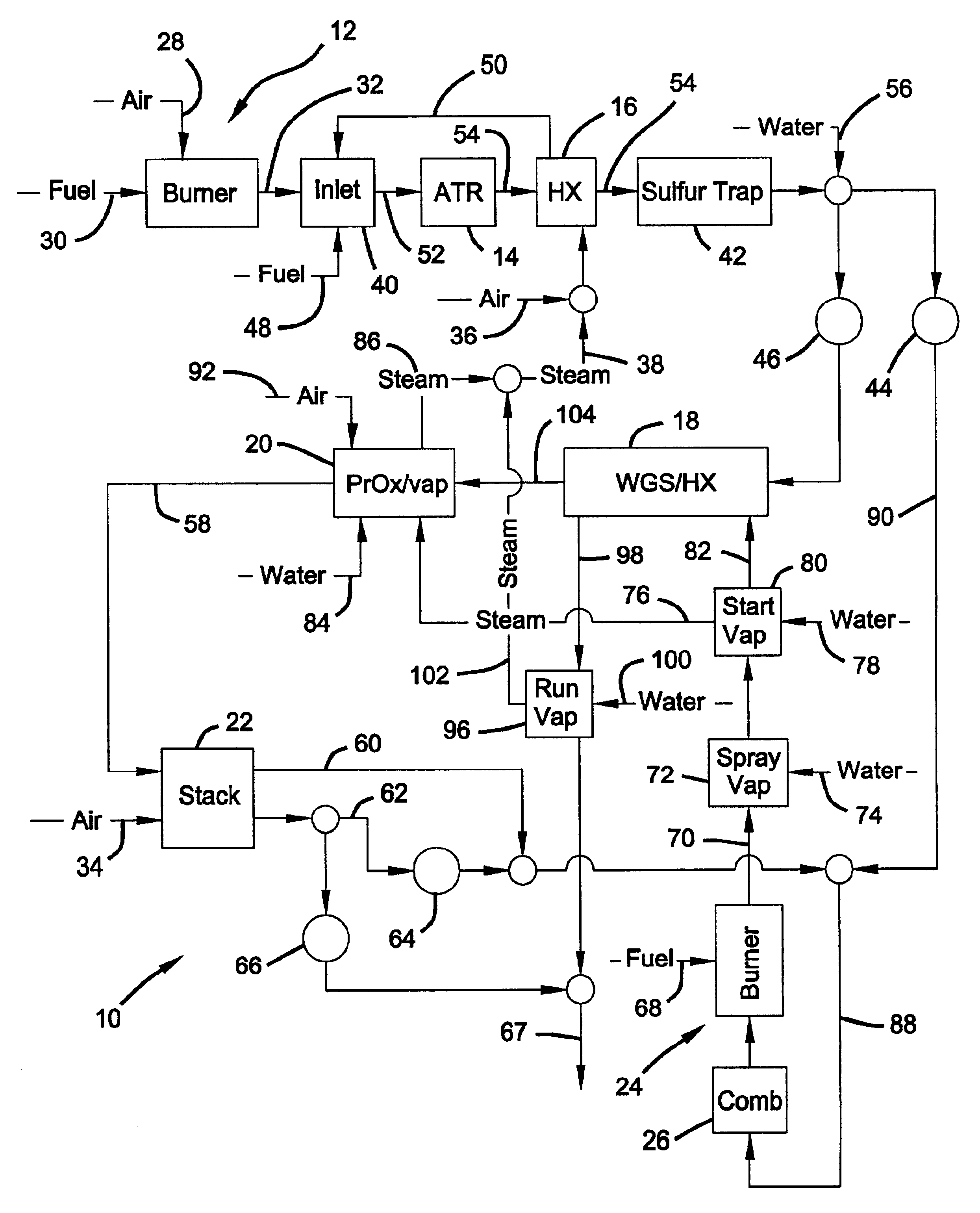
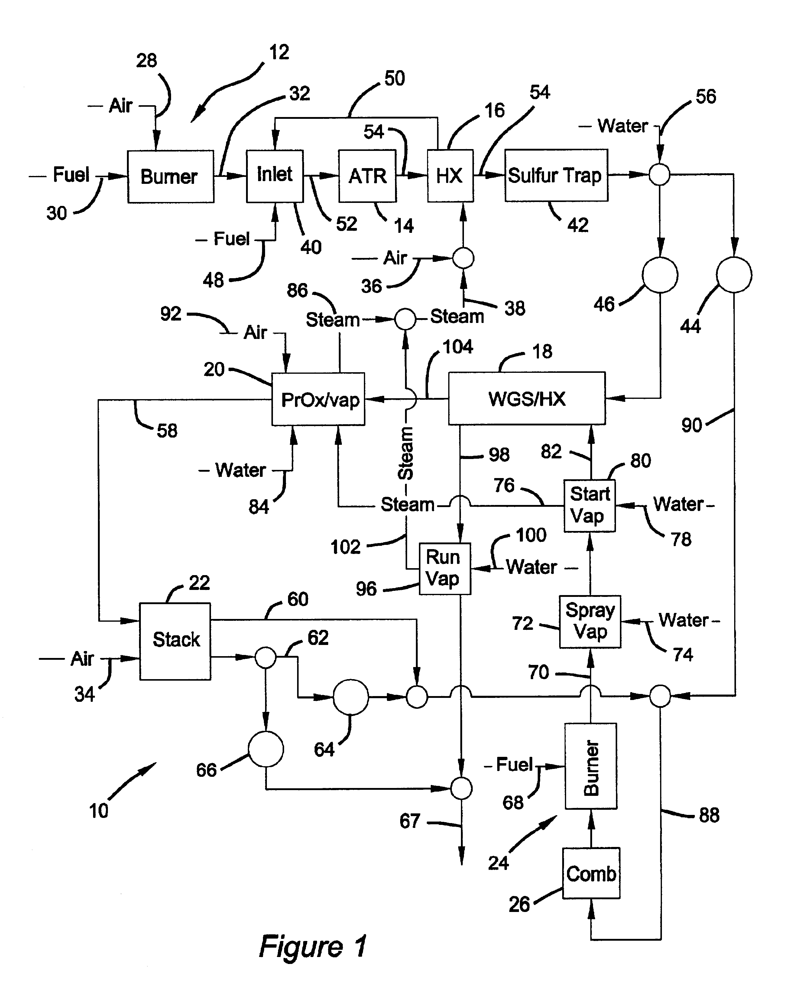
[0021]Referring to FIG. 1, a fuel processor, generally indicated as 10, according to a first embodiment of the present invention is illustrated. Fuel processor 10 generally includes a first burner system 12, an auto thermal reformer (reformer) 14, a heat exchanger 16, a water gas shift reactor / heat exchanger (WGS / HX) 18, a preferential oxidation / vaporizer (PrOx / vaporizer) reactor 20, a fuel cell stack 22, a second burner system 24, and a catalytic combustor (comb) reactor 26.

[0022]First burner system 12 and second burner system 24 are primarily used to heat the compone...


PUM

PropertyMeasurementUnit
temperaturesaaaaaaaaaa
operating temperatureaaaaaaaaaa

Abstract

A fuel processor for rapidly achieving operating temperature during startup. The fuel processor includes a reformer, a shift reactor, and a preferential oxidation reactor is provided for deriving hydrogen for use in creating electricity in a plurality of fuel cells. A first combustion heater system is coupled to at least one of the reformer, the shift reactor, and the preferential oxidation reactor to preheat the component during a rapid startup sequence. That is, the first combustion heater system is operable to produce thermal energy as a product of the combustion of air and fuel in the form of a first heated exhaust stream. This first heated exhaust stream is then used to heat the component directly or by using a heat exchanger type system. The first heated exhaust stream is also used by a second combustion device as a source of oxygen or diluent.

Description

FIELD OF THE INVENTION[0001]The present invention generally relates to fuel processors and, more particularly, relates to a fuel processor having a two-stage lean combustion system for rapid start of the fuel processor.BACKGROUND OF THE INVENTION[0002]H2—O2 fuel cells use hydrogen (H2) as a fuel and oxygen (as air) as an oxidant. The hydrogen used in the fuel cell can be derived from the reformation of a hydrocarbon fuel (e.g. methanol or gasoline). For example, in a steam reformation process, a hydrocarbon fuel (such as methanol) and water (as steam) are ideally reacted in a catalytic reactor (a.k.a. “steam reformer”) to generate a reformate gas comprising primarily hydrogen and carbon monoxide.[0003]An exemplary steam reformer is described in U.S. Pat. No. 4,650,727 to Vanderborgh. For another example, in an autothermal reformation process, a hydrocarbon fuel (such as gasoline), air and steam are ideally reacted in a combined partial oxidation and steam reforming catalytic reactor...

Claims


Application Information

Patent Timeline
Patent Type & Authority Patents(United States)
IPC IPC(8): B01B1/00C01B3/00C01B3/48F28C3/08F28C3/00C01B3/38H01M8/04H01M8/06H01M8/10
CPCB01B1/005C01B3/48F28C3/08H01M8/04022H01M8/0618H01M8/0668C01B2203/0244C01B2203/0283C01B2203/044C01B2203/047C01B2203/066C01B2203/0811C01B2203/0822C01B2203/0827C01B2203/0844C01B2203/1288C01B2203/142C01B2203/82Y02E60/50Y02P20/10
Inventor GOEBEL, STEVEN G.PETTIT, WILLIAM H.SENNOUN, MOHAMMED E.H.MILLER, DANIEL P.
Owner GM GLOBAL TECH OPERATIONS LLC
Learn More