Premixed prevaporized combustor
a combustor and prevaporization technology, applied in the field of premixed prevaporized combustor, can solve the problems of undesirable lag time for bringing the system on line, high carbon monoxide concentration, and insufficient shift reaction alone to reduce the co content of the reformate, and achieve the effect of rapid achieving operating temperatures during startup
- Summary
- Abstract
- Description
- Claims
- Application Information
AI Technical Summary
Benefits of technology
Problems solved by technology
Method used
Image
Examples
first embodiment
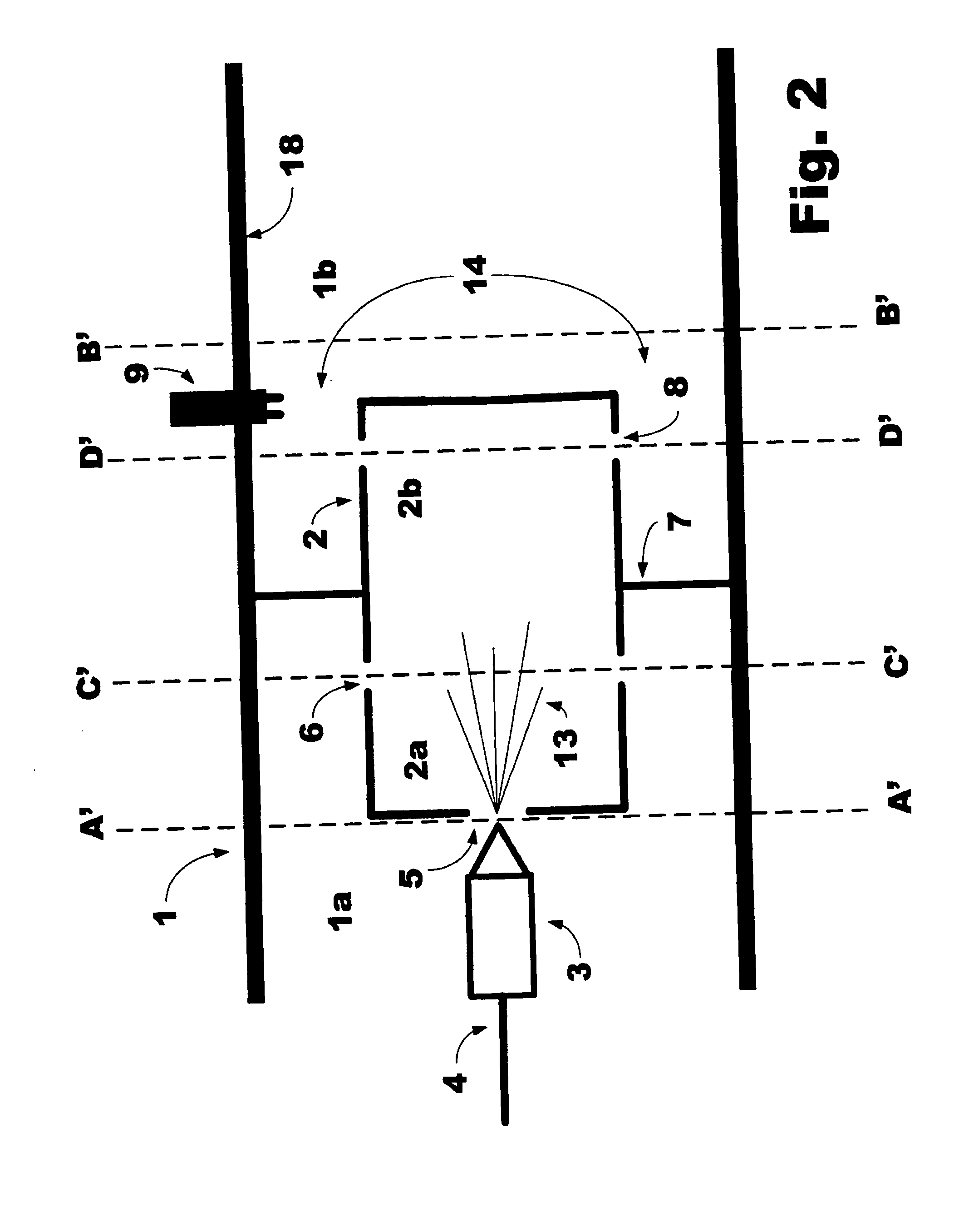
[0024] Referring to FIG. 2, a combustor 1 according to the present invention is illustrated. The combustor 1 generally includes a pre-mix / pre-evaporation chamber 2 (PPC) arranged and configured to extend into both a low temperature or cool portion 1a and a high temperature or hot portion 1b of the combustor, the demarcation between these two portions corresponding generally to a peripheral flange 7 extending from the PPC 2 toward the outer wall of the combustor 1.
[0025] The PPC 2 includes both a low temperature or cool portion 2a and a high temperature or hot portion 2b, a fuel injector 3 for injecting a liquid fuel from fuel line 4 through primary inlet 5 into the cool portion 2a of the PPC 2 with a characteristic spray pattern 13. Additional air is preferably introduced into the PPC 2 through one or more secondary inlets 6 arranged around the circumference of the cool portion 2a of the PPC 2. The fuel droplets emerging from the fuel injector 3 are thereby mixed with and at least p...
second embodiment
[0028] A second preferred embodiment of the present invention is illustrated in FIG. 4. In addition to the basic elements described above and illustrated in FIG. 2, this second embodiment includes an air inlet 10 and a channel 11 for introducing air around the combustor liner 18. With this arrangement, once a flame is established in the combustion zone 14, the air entering inlet 10 and flowing along the outside of the portion of combustor liner 18 enclosing the hot portion 1b of the combustor is preheated before entering the cool portion 1a of the combustor. The preheated air can be introduced into the cool portion 1a of the combustor through an axial inlet 15 and / or radial inlets 16 and into the cool portion 2a of the PPC 2 through inlets 5 and 6 to improve the evaporation of the fuel emerging from the fuel injector 3. In addition to preheating the air before mixing with the liquid fuel, the embodiment illustrated in FIG. 4 also provides some cooling for the portion of the combusto...
third embodiment
[0029] the present invention is illustrated in FIG. 6. In addition to the basic elements illustrated and discussed with respect to FIGS. 2 and 4, the combustor illustrated in FIG. 6 includes one or more gaps 17 between the periphery of the PPC flange 7 and the combustor liner 18 that will allow some portion of the air introduced into the cool portion 1a of the combustor to enter the hot portion 1b of the combustor without first passing through the PPC. If such gaps exist, however, they should be sized so that the portion of air flowing through gaps 17 is maintained at a sufficiently low level to ensure that the exit velocity of the combustion mixture exiting outlets 8 remains adequate to prevent flashback and that a stable flame may be maintained in the combustion zone 14.
[0030] A combustor according to the present invention is capable of quickly establishing a stable, non-sooting flame at both lean equivalence ratios between 0.3 and 1.0 and low-rich ratios between 1.0 and 1.2. Even...
PUM
 Abstract
Description
Claims
Application Information
 - R&D
- Intellectual Property
- Life Sciences
- Materials
- Tech Scout
- Unparalleled Data Quality
- Higher Quality Content
- 60% Fewer Hallucinations
Browse by: Latest US Patents, China's latest patents, Technical Efficacy Thesaurus, Application Domain, Technology Topic, Popular Technical Reports.
© 2025 PatSnap. All rights reserved.Legal|Privacy policy|Modern Slavery Act Transparency Statement|Sitemap|About US| Contact US: help@patsnap.com


