
Method for controlling a heating device for heating a component, control device and motor vehicle with same

a technology for heating components and control devices, applied in the direction of electrical control, process and machine control, instruments, etc., can solve the problems of sensor damage, sensor damage, and sensor damage, and achieve the effect of avoiding damage to sensors

Active Publication Date: 2020-01-28
VOLKSWAGEN AG
View PDF38 Cites 0 Cited by
  • Summary
  • Abstract
  • Description
  • Claims
  • Application Information

AI Technical Summary

Benefits of technology

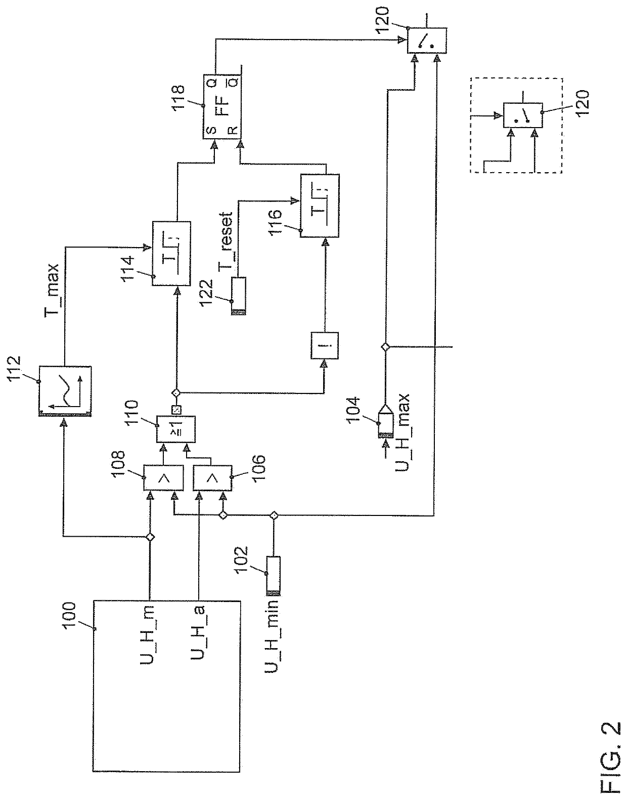
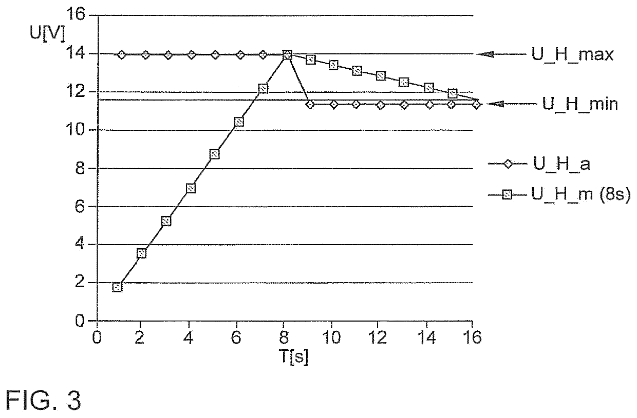
The patent text describes a method for heating a component without overheating it. The method involves controlling the heating voltage to prevent damage to the component while still getting the most out of the heating process. The method involves calculating the actual thermal loading of the component and adjusting the heating voltage accordingly to prevent damage. The heating device is initially operated at the maximum permissible heating voltage for the component, and if the temperature reaches the maximum, the heating voltage is reduced to the minimum to prevent damage. After a cool-down period, the heating device is operated again at the maximum permissible heating voltage to avoid rapid cooling of the component. This method ensures rapid and safe heating of components without damaging them.

Problems solved by technology

Otherwise, the sensor can be damaged as a result of high temperatures or thermal stresses.
This is necessary owing to the fact that damage can also occur as a result of heating voltages that are lower than the maximum permissible voltage, if they are applied over longer periods of time.
However, even if a sensor of this type is to be heated permanently using 13V, a maximum period of time is to be maintained and if said time limit is exceeded, it is to be expected that the sensor will be damaged.
Current strategies for heating sensors are confronted with the problem that it is not possible to predetermine in a precise manner the permissible heating parameters (maximum voltage and the maximum period of time of the maximum heating, but in particular the maximum period of time) in dependence upon different parameters.
As a consequence, the sensor is either heated excessively or the permissible parameters are specified with such a large safety margin that the operational readiness of the sensor is achieved later than necessary.

Method used


Image

  • Method for controlling a heating device for heating a component, control device and motor vehicle with same
  • Method for controlling a heating device for heating a component, control device and motor vehicle with same
  • Method for controlling a heating device for heating a component, control device and motor vehicle with same

Examples


Embodiment Construction

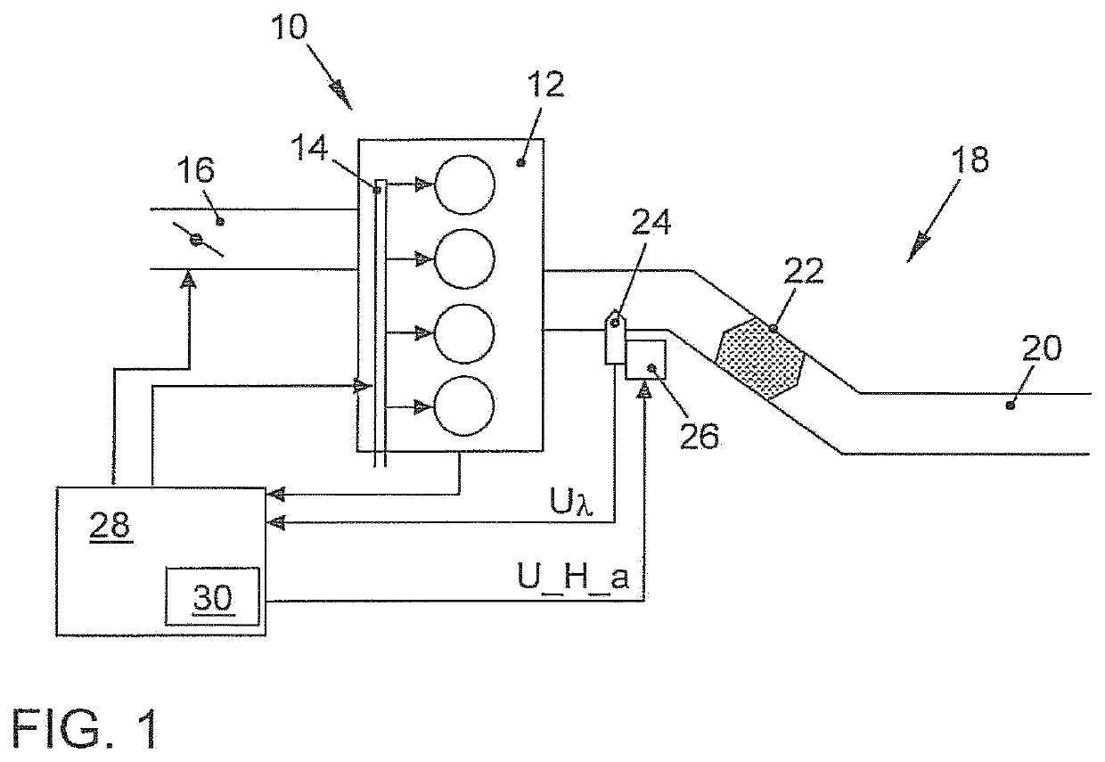
[0035]FIG. 1 illustrates a motor vehicle 10 of which in this figure only the internal combustion engine 12 and the exhaust gas system 18 that is connected thereto are illustrated.

[0036]The internal combustion engine 12 is supplied with fuel by way of a fuel supply system 14, for instance in the form of open-combustion chamber injection or an intake-manifold fuel injection. Moreover, combustion air is supplied by way of an air supply system 16 that comprises in particular an air intake manifold. If necessary, the quantity of air being supplied can be regulated by way of a controllable actuator, for example a throttle valve, which is arranged in the air intake manifold.

[0037]Exhaust gas that is generated by the internal combustion engine 12 is discharged into the environment by way of an exhaust duct 20 in the exhaust gas system 18, wherein exhaust gas components that would otherwise damage the environment are removed by means of one or several catalytic convertor(s) 22 and / or other e...


PUM


Abstract

A control device controls a heating device for heating a component, in particular a lambda sensor. The method comprises the cyclically repeating steps: operating the heating device at a heating voltage, ascertaining a current heating voltage (U_H_a) of the heating device, ascertaining a mean heating voltage (U_H_m) for a predetermined, immediately preceding period of time, determining a maximum permissible heating period (T_max) for which the component may be heated for the maximum length of time using the current heating voltage (U_H_a) or using the mean heating voltage (U_H_m), in dependence upon the mean heating voltage (U_H_m), comparing the current heating voltage (U_H_a) and the mean heating voltage (U_H_m) with a predetermined minimum heating voltage (U_H_min), and reducing the heating voltage of the heating device if the current heating voltage (U_H_a) and / or the mean heating voltage (U_H_m) exceeds the predetermined minimum heating voltage (U_H_min) for the duration of the maximum permissible heating period (T_max).

Description

CROSS-REFERENCE TO RELATED APPLICATIONS[0001]This application is a National Phase Application of PCT International Application No. PCT / EP2013 / 053665, International Filing Date Feb. 25, 2013, which claims priority to German Patent Application No. 10 2012 203 401.3, filed Mar. 5, 2013, each of which are hereby incorporated by reference.BACKGROUND OF THE INVENTION[0002]The invention relates to a method for controlling a heating device for heating a component, in particular an exhaust gas sensor. The invention further relates to a correspondingly designed control device and a motor vehicle that comprises a control device of this type for controlling a heating device for heating a component, in particular an exhaust gas sensor.[0003]It is known to control or to regulate internal combustion engines in dependence upon a composition of their exhaust gases, wherein the corresponding exhaust gas component is measured by means of a suitable exhaust gas sensor. In particular, the air-fuel ratio...

Claims


Application Information

Patent Timeline
Patent Type & Authority Patents(United States)
IPC IPC(8): H05B1/02
CPCH05B1/0236F02D41/1494G05D23/1909G05D23/24
Inventor HAHN, HERMANN
Owner VOLKSWAGEN AG
Learn More