Edge coated gaskets and method of making same
a gasket and edge coating technology, applied in the field of gaskets, to achieve the effect of avoiding avoiding the failure modes of traditional gaskets, and maximizing the tolerance to flange surface imperfections (roughness, warping, deflection)
- Summary
- Abstract
- Description
- Claims
- Application Information
AI Technical Summary
Benefits of technology
Problems solved by technology
Method used
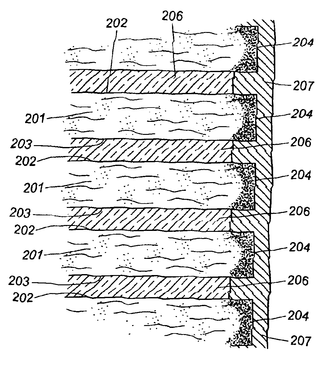
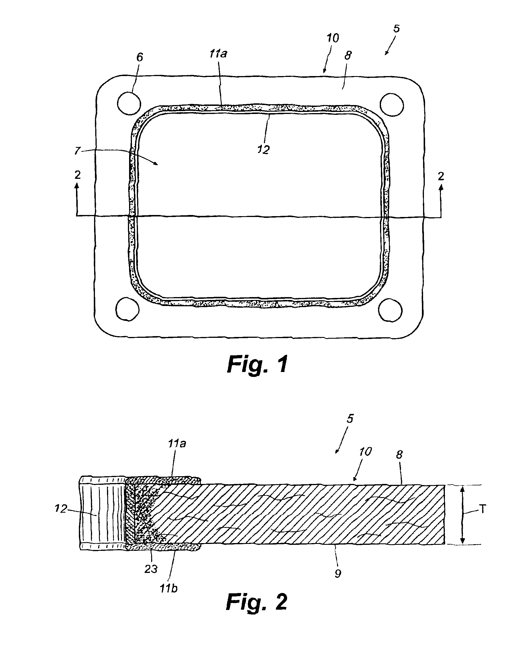
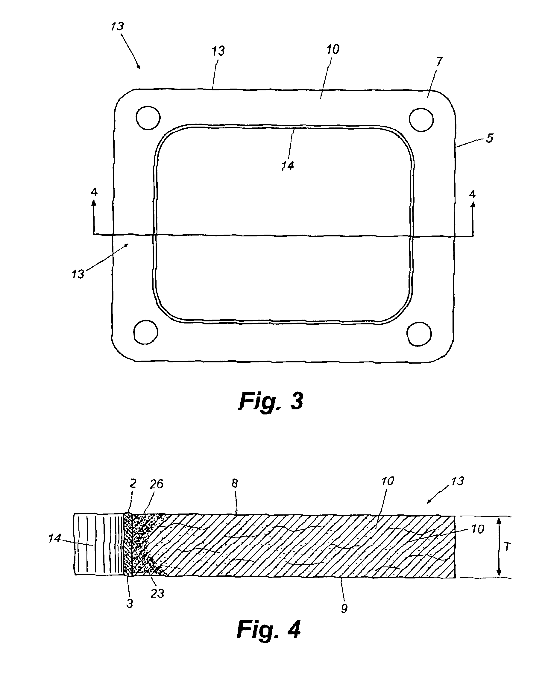
Image

Examples
example 1
[0131]A. Crush Test—ASTM F1574-95
[0132]In this example, a crush test was performed on gasket samples prepared in accordance with the present invention using test standard ASTM F1574-95, which is an industry standard for testing the compression strength of a gasket under elevated temperatures. Each gasket was subjected to a controlled amount of flange pressure at 300 degrees Fahrenheit under uniform load conditions. The deformation of the sample as a percentage increase in surface area over the original gasket surface area was then measured. To prepare test gaskets, identical annular gaskets were cut from a cellulose-based paper gasket sheet material. Each gasket included upper and lower opposing faces, an interior edge defining an aperture, and an outer peripheral edge. The gaskets had an inner diameter of 0.515 inches, an outer diameter 0.950 inches, and a resulting flange width of 0.2175 inches.
[0133]Table 1 shows the results of the crush test in terms of the change in gasket area...
example 2
[0142]In the test of this example, the sealability effectiveness of edge coatings was measured. Identical gasket base sheets were obtained from the same gasket sheet material. Each gasket included opposed faces and an interior edge surrounding and defining an aperture of the gasket. Gasket A was left completely uncoated and represents the control in this test. A second gasket, gasket B, was provided with an edge coating only on the interior edge of the base sheet. The edge coating comprised a commercially available NBR latex material.
[0143]A high-pressure sealability test was performed on gaskets A and B. The gaskets were placed between the flanges connecting two halves of the cylinder and the flanges were tightened to compress the gaskets with the indicated flange pressures. The cylinder was then pressurized with nitrogen to a pressure of 225 PSI for one hour. The pressure remaining in the cylinder after one hour was then measured and noted as indicated in the chart below. Gaskets ...
example 3
[0146]In this test, the same gaskets tested for sealability in Example 2, were subjected to the crush test described in Example 1. Uncoated gasket A served as the control. Gasket B was provided with an edge coating as described. The two gaskets were then subjected to the crush test described above. The results of the test, in units of percent change in surface area of the gaskets, are outlined in Table 3.
[0147]
TABLE 4Percentage Area Change as a Function of Flange PressureGasket5,000 PSI10,000 PSI15,000 PSIA uncoated11016B edge coated2 916
The results of this test demonstrate that the edge coated gasket, which demonstrates exceptional sealability as shown in Example 2, also exhibits compression failure resistance substantially unchanged from a bare uncoated gasket (gasket A). Compression failure resistance of the two was the same at 15,000 PSI flange pressures. Conclusions to be drawn from this example in conjunction with the test of Example 2 are that edge coated gaskets according to...
PUM
 Abstract
Description
Claims
Application Information
 - R&D
- Intellectual Property
- Life Sciences
- Materials
- Tech Scout
- Unparalleled Data Quality
- Higher Quality Content
- 60% Fewer Hallucinations
Browse by: Latest US Patents, China's latest patents, Technical Efficacy Thesaurus, Application Domain, Technology Topic, Popular Technical Reports.
© 2025 PatSnap. All rights reserved.Legal|Privacy policy|Modern Slavery Act Transparency Statement|Sitemap|About US| Contact US: help@patsnap.com