Optical module

a technology of optical modules and output beams, applied in the field of optical modules, can solve the problems of reducing the quantity of output beams, axis deviation, and the deviation of optical axes, and achieve the effect of suppressing the tracking error

Inactive Publication Date: 2005-07-19
MITSUBISHI ELECTRIC CORP
View PDF21 Cites 1 Cited by
  • Summary
  • Abstract
  • Description
  • Claims
  • Application Information

AI Technical Summary

Benefits of technology

[0010]It is an object of this invention to provide an optical module capable of suppressing the tracking error.

Problems solved by technology

One of the causes of the tracking error is the deviation of the optical axis (optical axis deviation).
This reduced quantity of the output beam becomes a factor of the tracking error.
The tracking error causes a variation in the gain of the optical fiber amplifier, and this becomes a serious problem in the optical communications.
Since the APC circuit performs the power control based on such monitoring current, there is a problem that the tracking error becomes large.

Method used


Image

  • Optical module
  • Optical module
  • Optical module

Examples


Embodiment Construction

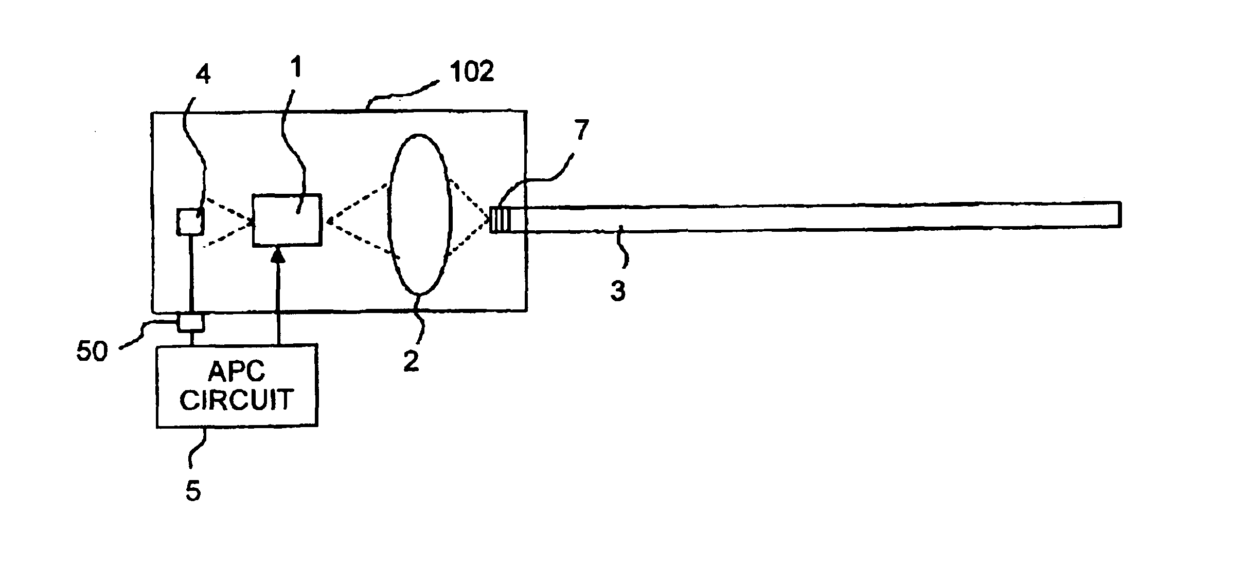
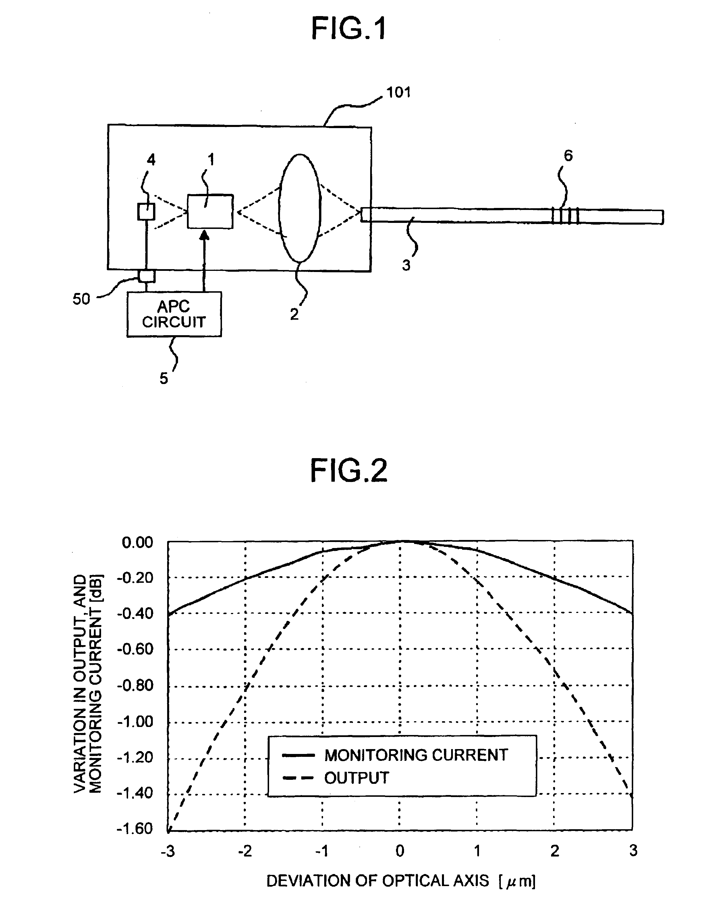
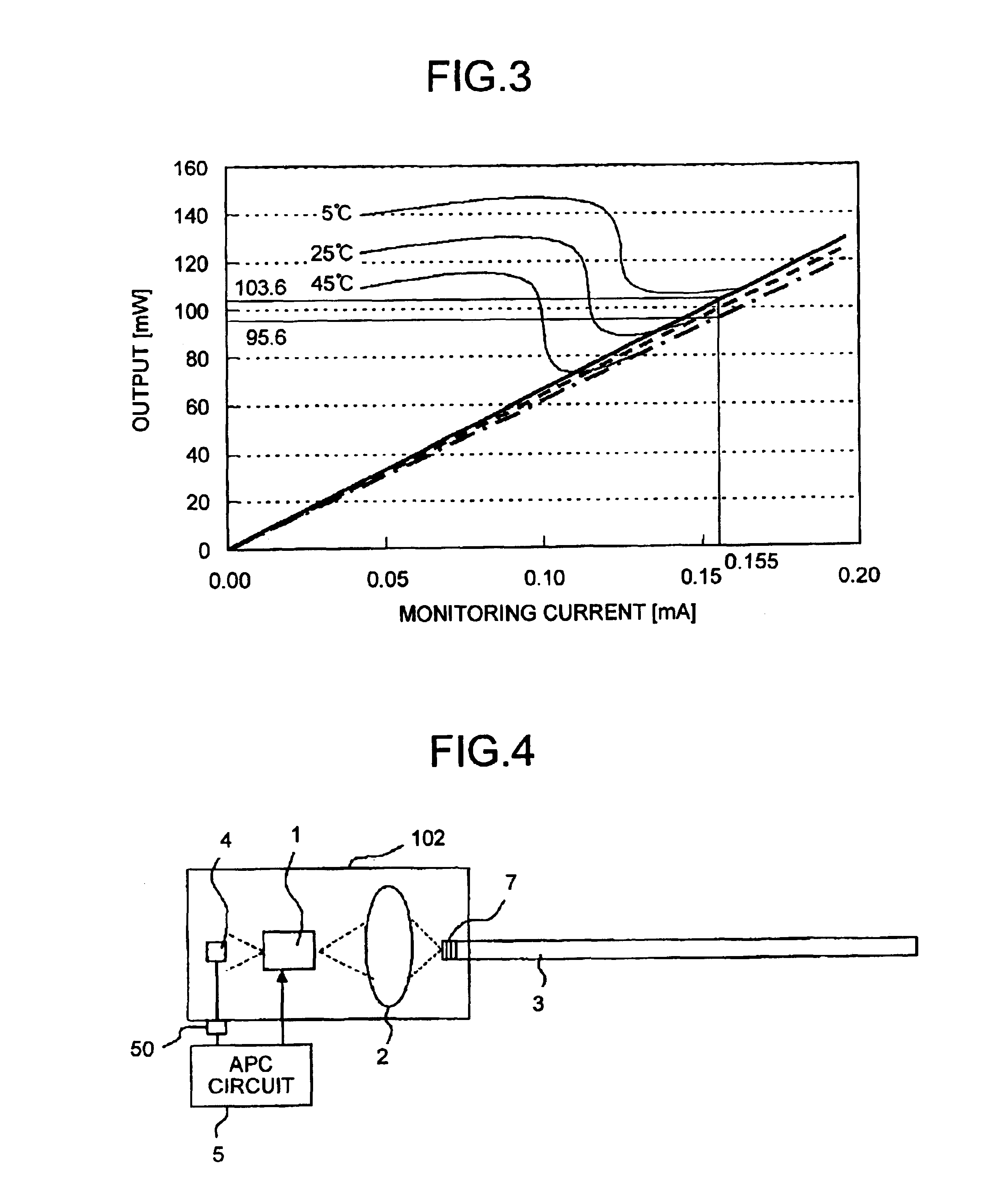
[0023]FIG. 1 is a diagram that shows a structure of an optical module 101 relating to an embodiment of the present invention. In FIG. 1, reference numerals 1 to 5, and 50 denote constituent parts of the optical module identical to those of the conventional technique. A reference numeral 6 denotes a fiber grating that has a diffraction grating provided in the optical fiber 3 and is used as a feedback section that reflects a part of a beam and passes or absorbs the rest of the beam.

[0024]The operation of the optical module 101 is explained below. The laser diode 1 emits the front laser beam. The lens 2 focuses the first laser beam. The optical fiber 3 transmits the focused beam. The fiber grating 6 reflects a part of the beam incident to the optical fiber, and passes the rest of the beam. The reflected part of the laser beam is passes through the lens 2 and the laser diode 1 and, falls on the photodiode 4. When the fiber-end beam output changes due to a deviation of the optical axis, ...


PUM


Abstract

An optical fiber that transmits laser beams generated by a laser diode in an optical module is provided with a fiber grating. The fiber grating passes most of the laser beams and reflects some of them to a photodiode provided on the back side of the laser diode. The photodiode also receives scattered laser beams from the laser diode. The photodiode outputs a current equivalent to the amount of received laser beams. An APC circuit controls emission of laser beams by the laser diode based on this current.

Description

BACKGROUND OF THE INVENTION[0001]1) Field of the Invention[0002]The present invention relates to an optical module that has an optical fiber and a laser diode optically coupled together, and includes a monitoring photodiode that receives a beam emitted from the back side of the laser diode.[0003]2) Description of the Related Art[0004]In the optical communications, an optical fiber amplifier, which employs an EDF (Er-doped optical fiber), is used for amplifying the optical signal transmitted through the optical fiber. This optical fiber amplifier has an optical module as a light source and, amplifies the light generated by the optical module. FIG. 7 shows a structure of a conventional optical module 100. A reference numeral 1 denotes a laser diode (LD) that emits a laser beam from the front side (front laser beam) and the back side (back laser beam) thereof, and 2 denotes a lens that focuses the front laser beam. A reference numeral 3 denotes an optical fiber that transmits the laser...

Claims


Application Information

Patent Timeline
Patent Type & Authority Patents(United States)
IPC IPC(8): H01S5/00H01S5/022H01S5/14G02B6/42
CPCH01S5/02248H01S5/146H01S5/0683H01S5/147H01S5/02325
Inventor FUJITA, TAKESHI
Owner MITSUBISHI ELECTRIC CORP
Why Eureka
Try Eureka