
Method for making reduced iron

a technology of reduced iron and reduction iron, which is applied in the field of making reduced iron, can solve the problems of significant pulverization, difficult handling of the resulting reduced iron product, and pellet breaking into chips, and achieves the effects of reducing iron products, high zinc removal rate, and high metallization degr

Inactive Publication Date: 2005-07-19
KOBE STEEL LTD
View PDF31 Cites 5 Cited by
  • Summary
  • Abstract
  • Description
  • Claims
  • Application Information

AI Technical Summary

Benefits of technology

[0010]The present invention aims to overcome the above-described problems. An object of the present invention is to provide a method for making reduced iron whereby breaking of agglomerates containing blast-furnace sludge into pieces and / or fines is avoided inside the furnace, reduced iron products of high metallization degrees can be produced at high yield, and high-grade zinc material, i.e., crude zinc oxide, can be recovered during the course.
[0016]Preferably, in the disintegrating step, the blast-furnace sludge containing pseudoparticles having a diameter exceeding 1 mm is disintegrated to reduce the mass ratio of the pseudoparticles having a diameter exceeding 1 mm to the mixed material to 50% or less.
[0022]According to the present invention, pellets can be prevented from breaking into chips and fines during reduction, and reduced iron products having a high zinc removal rate and a high metallization degree can be produced at a high yield. Moreover, the quality of zinc oxide recovered from the exhaust gas of the furnace can be dramatically improved.

Problems solved by technology

However, when pellets contain blast-furnace sludge, the pellets break into chips and fines when they are fed inside the rotary hearth furnace even though they are dried to a water content of 1 percent by mass or less.
As a result, a significant degree of pulverization occurs, and handling of the resulting reduced iron product becomes extremely difficult.
This results in a decrease in metallization degree of the resulting reduced iron product, a decrease in zinc-removal rate, and a decrease in yield.
Furthermore, a large amount of iron oxide becomes mixed in the recovered crude zinc oxide, thereby degrading the quality as the zinc oxide material.
However, since blast-furnace sludge expands during reduction as described below, breaking of the compacts cannot be effectively prevented by merely avoiding bursting resulting from water evaporation.
Moreover, since the compacts are dried on the rotary hearth before reduction, the compacts remain in the furnace for a long time, thereby requiring a large hearth and a large-scale reduction plant.

Method used


Image

  • Method for making reduced iron
  • Method for making reduced iron
  • Method for making reduced iron

Examples


first embodiment

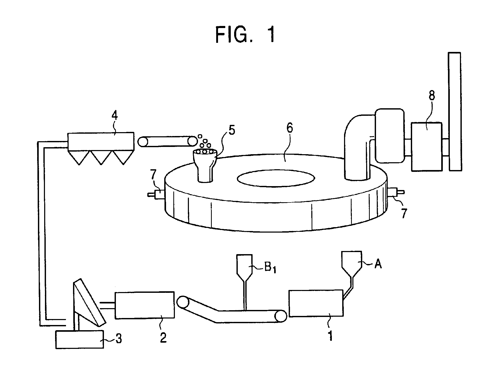
[0037]FIG. 1 is a schematic diagram showing a plant by which a method of the present invention for making reduced iron (a method for making crude zinc oxide) using blast-furnace sludge is implemented.

[0038]As has been previously described, since blast-furnace sludge having a high water content may contain a large number of pseudoparticles, the blast-furnace sludge is preferably disintegrated in advance. Referring to FIG. 1, blast-furnace sludge A containing pseudoparticles having a diameter exceeding 1 mm is disintegrated using a disintegrator 1 so that the ratio of the pseudoparticles to the mixed material prepared as below becomes 50 percent by mass or less (disintegrating step). Examples of the disintegrator 1 include a rod mill, a ball mill, and a jaw crusher.

[0039]An iron-oxide-containing powder B1 containing iron oxides is added to the disintegrated blast-furnace sludge A. Examples of the iron-oxide-containing powder B1 include iron ore powder, and steel mill wastes such as ba...

second embodiment

[0049]A second embodiment of the present invention will now be described with reference to FIG. 2. In the mixing step of the first embodiment described above, a carbonaceous powder B2 containing carbon may be added instead of or in addition to the iron-oxide-containing powder B1. Here, the mixture of the iron-oxide-containing powder B1 and the carbonaceous powder B2, and the carbonaceous powder B2 alone are collectively referred to as a powder material B containing either carbon or carbon and iron oxide. Examples of the carbonaceous powder B2 include coal powder, coke powder, petroleum coke powder, coke dry quencher (CDQ) powder, charcoal powder, carbide powder of wastes, and blast-furnace dry dust. The amount of the powder material B added is adjusted to satisfy relationship (2):

Sc≦8−2NL+0.02YD  (2)

wherein Sc=XC−(12 / 16)·XO, NL represents the average number of the agglomerate (pellet) layers on the hearth, YD=100XCB / XC, XC is a carbon content (percent by mass) in the dried agglomera...

third embodiment

[0053]Referring to FIG. 1, blast-furnace sludge A containing pseudoparticles having a diameter exceeding 1 mm is disintegrated using a disintegrator 1 until the ratio of the pseudoparticles having a diameter exceeding 1 mm to the mixed material is 50 percent by mass or less (disintegrating step). Examples of the disintegrator include crushers and grinders such as a roll mill, a rod mill, a ball mill, and a jaw crusher. A powder material B containing iron oxides is blended into the disintegrated blast-furnace sludge A. Examples of the powder material B include steel mill wastes such as iron ore powder, basic-oxygen-furnace dust, electric-furnace dust, mill scale, and mill sludge. Water may also be added if necessary. Furthermore, a carbonaceous substance such as coal, coke, petroleum coke, or the like, or a binder such as starch, bentonite, or the like may be added. The resulting mixture is mixed in a mixer 2 so as to prepare a mixed material (mixing step). Examples of the mixer 2 in...


PUM

PropertyMeasurementUnit
Lengthaaaaaaaaaa
Fractionaaaaaaaaaa
Percent by massaaaaaaaaaa

Abstract

A method for making reduced iron using blast-furnace sludge is provided. The method includes a mixing step of mixing the blast-furnace sludge and an iron-oxide-containing powder to prepare a mixed material, an agglomerating step of agglomerating the mixed material to form agglomerates, a feeding step of feeding the agglomerates onto a continuously moving hearth, and a reducing step of heating the agglomerates to remove zinc and reduce the agglomerates.

Description

BACKGROUND OF THE INVENTION[0001]1. Field of the Invention[0002]The present invention relates to a method for making reduced iron using blast-furnace sludge.[0003]2. Description of the Related Art[0004]Blast-furnace dust can be classified into relatively coarse dry dust collected by a dry system and sludge consisting of fine particles collected by a wet system. Dry dust has a relatively low zinc content when compared with that of sludge, and can be recycled as the material for sintered ore. In contrast, sludge having a high zinc content requires zinc-removing processes before being recycled as a blast-furnace feed material.[0005]Recently, various methods for processing dust have been investigated. As a result of the investigation, a rotary hearth furnace method including the steps of agglomerating a mixture of an iron-oxide-containing substance, such as iron ore or dust, and a carbonaceous reductant and heating the resulting agglomerates in a rotary hearth furnace so as to obtain re...

Claims


Application Information

Patent Timeline
IPC IPC(8): C22B5/10C22B5/16C22B5/00C21B13/00C21B13/10C22B19/30C22B1/14C22B1/245C22B19/00
CPCC21B13/0046C21B13/105C22B1/245C22B5/10C22B5/16C22B19/30Y02P10/20
Inventor MAKI, TAKESHIMATSUI, YOSHIYUKISUGIYAMA, TAKESHIHARADA, TAKAOTETSUMOTO, MASAHIKOTAMAZAWA, HIROSHIUEDA, TADASHIMORIOKA, KOICHIIWASAKI, NOBUYUKITANAKA, HIDETOSHIFUJI, KOJIROSUGITATSU, HIROSHI
Owner KOBE STEEL LTD
Learn More