
System for transrenal/intraostial fixation of endovascular prosthesis

a technology for endovascular prosthesis and fixation system, which is applied in the field of tubular prosthesis, can solve the problems of high mortality rate, complicated surgical procedure, and difficult to secure the fixation of the prosthesis

Inactive Publication Date: 2005-07-19
MEDTRONIC VASCULAR INC
View PDF13 Cites 71 Cited by
  • Summary
  • Abstract
  • Description
  • Claims
  • Application Information

AI Technical Summary

Benefits of technology

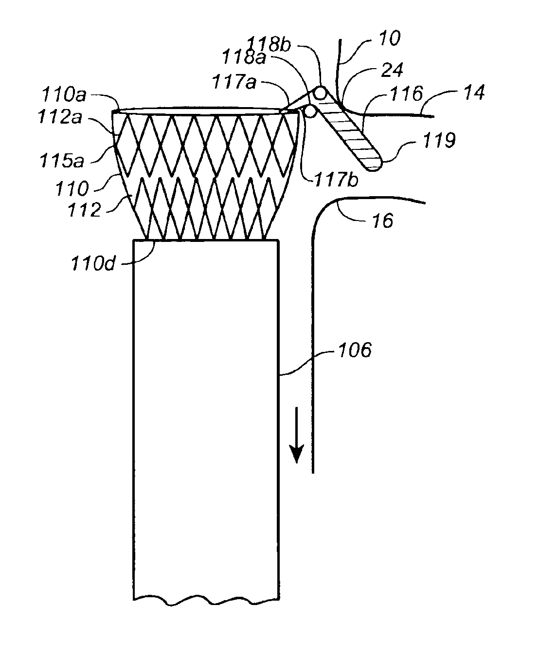
[0009]An embodiment according to the present invention provides an endoluminal prosthesis with an improved fixation system for deploying the endoluminal prosthesis within a body lumen and reducing distal migration of the prosthesis. The fixation system comprises at least one laterally extending member or finger member extending from a portion of a prosthesis, where the finger member is to be deployed within a proximal branch lumen. The finger member may be incorporated into the main prosthesis or may be included with a modular portion of the prosthesis such as a short cuff that is initially deployed within the body lumen, with the longer main prosthesis subsequently fixed to the cuff. The finger member is configured to be non-piercing or relatively atraumatic to tissue. The finger member may be a self-expanding so that it tends to open or extend laterally when not constrained. In one embodiment, the finger member extends laterally at about 90 degrees from the prosthesis.
[0010]In one embodiment a modular fixation device or cuff is provided with at least one intraostial finger member. The cuff is configured for initial fixation to a lumen wall. A longer endoluminal prosthesis is provided and is coupled to the cuff to bypass a diseased portion of the anatomy. The cuff may provide a more reliable landing zone for the prosthesis and a more predictable, consistent engagement area, while the finger further prevents distal migration of the cuff. In one embodiment, the cuff comprises one or more support structures and a graft material surrounding at least a portion of a support structure. The cuff is arranged to engage the inner lumen wall at a fixation site and form a leak resistant seal with the inner wall of the body lumen. The finger member when deployed extends laterally from the sidewall of the tubular member and into the branch vessel.
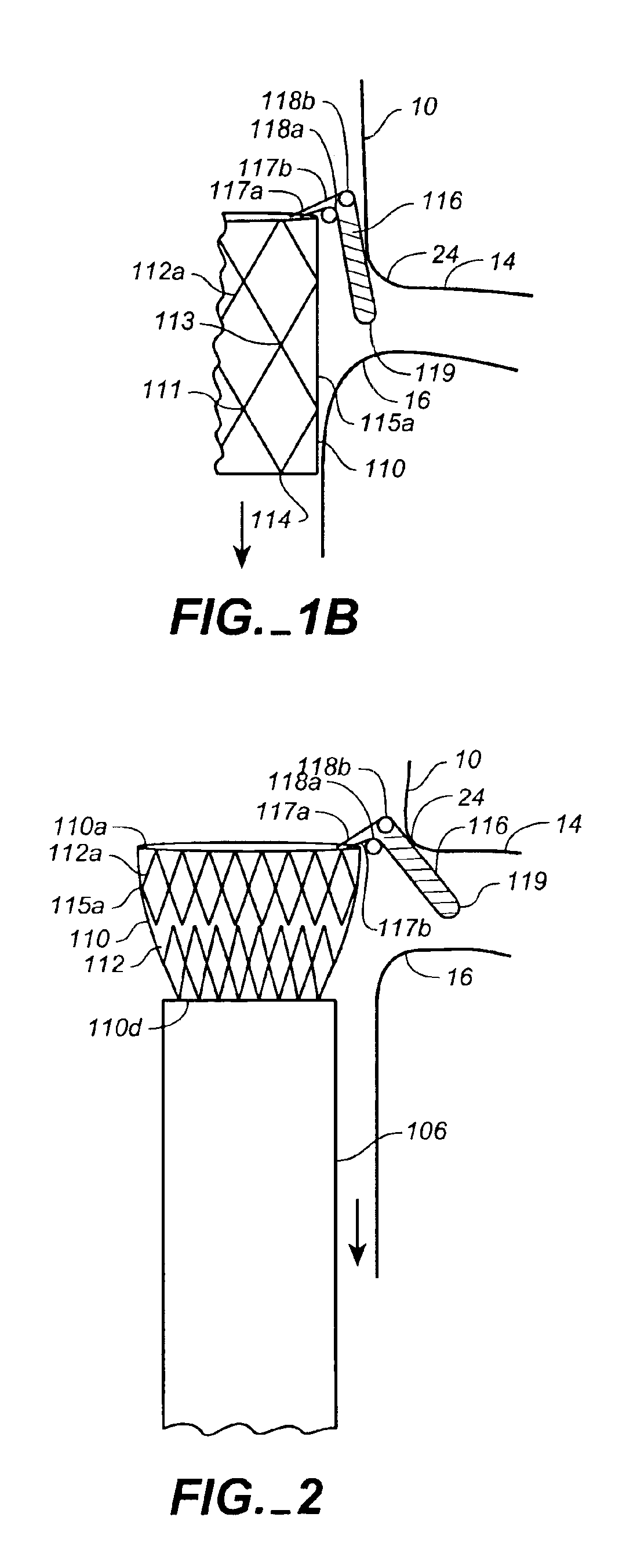
[0014]The annular support members each comprise an annular expandable member formed by a series of connected compressible diamond structures. The finger member is preferably coupled to the proximal most annular support member and may be integrally formed therewith so that it extends about 1 or 2 millimeters above the renal ostium, which is not to be blocked by the prosthesis. Alternatively, for example, the expandable member may be formed of an undulating or sinusoidal-like patterned wire ring or other compressible spring member. Preferably the annular support members are radially compressible springs biased in a radially outward direction, which when released, bias the prosthesis into conforming fixed engagement with an interior surface of the vessel. Annular support members are used to create a seal between the prosthesis and the inner wall of a body lumen, as well as to support the tubular graft structures. The annular springs are preferably constructed of Nitinol. Examples of such annular support structures are described, for example, in U.S. Pat. Nos. 5,713,917 and 5,824,041 incorporated herein by reference. When used in an aneurysm exclusion device, the springs have sufficient radial spring force and flexibility to conformingly engage the body lumen inner wall to avoid excessive leakage, and prevent pressurization of the aneurysm, i.e., to provide a leak resistant seal. Although some leakage of blood or other body fluid may occur into the aneurysm isolated by the prosthesis, an optimal seal will reduce the chances of aneurysm pressurization and the possible resulting rupture. The annular support members are attached or mechanically coupled to the graft material along the tubular graft by various means, such as, for example, by stitching onto either the inside or outside of the tubular graft.
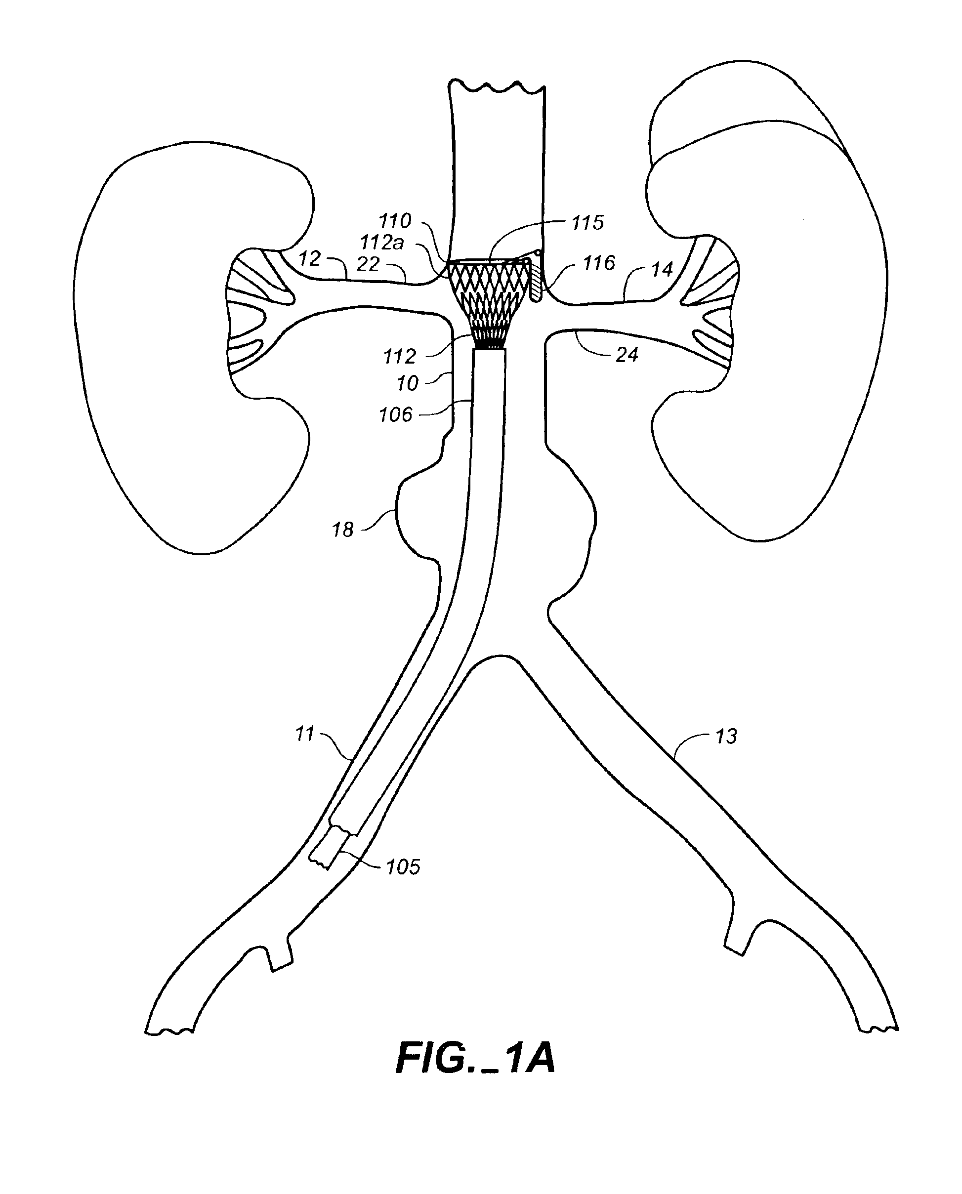
[0018]A guide wire may be initially inserted through the femoral artery to the aorta and into the renal artery where the finger of the prosthesis is to be deployed. This may assist in locating the distal end of the sheath at the ostium of the renal artery where the finger member of the prosthesis is to be deployed Once appropriately located, a sheath on the catheter covering or restraining the prosthesis is retracted to release the finger member. Once the finger member is appropriately located in the ostium, the sheath may be further retracted releasing the prosthesis, allowing the annular springs to expand and attach or engage the prosthesis to the inner wall of the body lumen. Alternatively, the prosthesis may be positioned and released with the finger member slightly above the ostium. The finger member expands when released and may be constrained to some extent by the inner wall of the lumen. The free end of the finger member is located at the ostium of a branch vessel by drawing the prosthesis distally until the finger member is located in the ostium. Once the finger member is in position, the prosthesis may be fully deployed and released from the catheter. A marker may be placed on the prosthesis so that the circumferential orientation of the finger member may be determined for positioning it at the ostium of the side or branch vessel.

Problems solved by technology

The surgical procedure is complex and requires long hospital stays due to serious complications and long recovery times and has high mortality rates.
Although frequently referred to as stent-grafts, these devices differ from covered stents in that they are not used to mechanically prop open natural blood vessels.
In general, in many diseased vessels, the area for prosthesis fixation above an aneurysm or other diseased portion may be limited, making secure fixation of the prosthesis more difficult.
In addition, over time there is a possibility that the prosthesis may migrate.
However, particularly in a diseased patient, there may be suprarenal cholesterol or atheroma plagues that may dislodge, fragment or release from the supra renal area.
The hooks traumatize the tissue and therefore may be undesirable.
However, in some patients, migration may occur when the neck or region in which the graft is deployed expands or otherwise changes over time and thus increased radial force may not prevent migration in such a situation.

Method used


Image

  • System for transrenal/intraostial fixation of endovascular prosthesis
  • System for transrenal/intraostial fixation of endovascular prosthesis
  • System for transrenal/intraostial fixation of endovascular prosthesis

Examples


Embodiment Construction

[0033]FIGS. 1A-8 illustrate various embodiments of a cuff with a finger member or extension, and endoluminal prosthesis, a delivery system and a method according to the present invention. Although a fixation cuff, endoluminal prosthesis, delivery system and method according to the invention may be used in any body lumen that conducts body fluid and may be used as a single lumen prosthesis or a multibranch prosthesis, they are described herein with reference to treatment of an aortic aneurysm, in particular in the abdomen of a patient using a bifurcated prosthesis.

[0034]FIGS. 1A-3 and 7 illustrate an embodiment of a fixation cuff according to the present invention. The cuff 110 comprises a tubular graft layer 115, a series of radially compressible annular support members 112 attached to the tubular graft layer 115, and a finger member 116 extending laterally of the proximal most support member 112a. The finger member 116 is welded to the proximal most support member 112a and is confi...


PUM


Abstract

An endoluminal prosthesis is provided with an improved fixation system for coupling the endoluminal prosthesis to an inner wall of a lumen and to reduce distal migration. According to an embodiment of the present invention, a laterally protruding member atraumatically engages the ostium of a side or branch vessel. The protruding member may be fixed to a portion of a prosthesis. In one embodiment the protruding member is provided on a modular fixation device for initial fixation within the body lumen with the finger member within the side or branch vessel. A primary endoluminal prosthesis is then fixed to the modular fixation device to bypass a diseased portion of the anatomy.

Description

FIELD OF THE INVENTION[0001]The present invention relates to tubular prostheses such as grafts and endoluminal prostheses including, for example, stent-grafts and aneurysm exclusion devices, and methods for placement of such grafts and endoluminal structures. In particular, the present invention relates to a system for intraostial endoluminal prosthesis fixation.BACKGROUND OF THE INVENTION[0002]A wide range of medical treatments have been previously developed using “endoluminal prostheses,” which terms are herein intended to mean medical devices which are adapted for temporary or permanent implantation within a body lumen, including both naturally occurring or artificially made lumens. Examples of lumens in which endoluminal prostheses may be implanted include, without limitation: arteries such as those located within coronary, mesentery, peripheral, or cerebral vasculature; veins; gastrointestinal tract; biliary tract; urethra; trachea; hepatic shunts; and fallopian tubes. Various ...

Claims


Application Information

Patent Timeline
Patent Type & Authority Patents(United States)
IPC IPC(8): A61F2/06
CPCA61F2/07A61F2/848A61F2002/061A61F2002/067A61F2002/075A61F2002/8486A61F2/89A61F2/90A61F2230/0054
Inventor LETORT, MICHEL
Owner MEDTRONIC VASCULAR INC
Learn More