Eureka AIR delivers breakthrough ideas for toughest innovation challenges, trusted by R&D personnel around the world.

Capacitance meter

a technology of capacitance meters and meter bodies, applied in the direction of instruments, volume meters, liquid/fluent solid measurements, etc., can solve the problems of hampered practical application in an industrial environment, specific requirements for applications in the oil industry, and unsatisfactory results

Inactive Publication Date: 2005-07-12
SHELL OIL CO
View PDF11 Cites 9 Cited by
  • Summary
  • Abstract
  • Description
  • Claims
  • Application Information

AI Technical Summary

Benefits of technology

The present invention provides a method for determining the flow property of a fluid flowing through a conduit using a capacitance meter. The method involves measuring capacitances at different locations in the conduit and calculating cross correlations between these capacitances. By using a set of measurement capacitors and measuring at several moments during a time interval, the method reduces the number of cross correlations needed to be determined, resulting in a much faster processing speed and increased efficiency. The invention also includes a calibration method for correcting for environmental influences on the sensor readings. Overall, the invention provides a more efficient and accurate method for determining the flow property of fluids in flow velocity tomography.

Problems solved by technology

There are, however, a number of problems associated with capacitance flow meters, that have so far hampered their practical application in an industrial environment.
For example, specific requirements for applications in the oil industry, where the flow of a multi-component fluid is to be monitored, have not yet been met.
This presents an immense computational challenge requiring high-performance data-processing devices, e.g. special purpose devices such as a parallel-processor.
Thus, in the absence of a far more efficient method for processing the data, the need for high-performance data-processing devices will impede the practical application in an industrial environment.

Method used


Image

  • Capacitance meter
  • Capacitance meter
  • Capacitance meter

Examples


Embodiment Construction

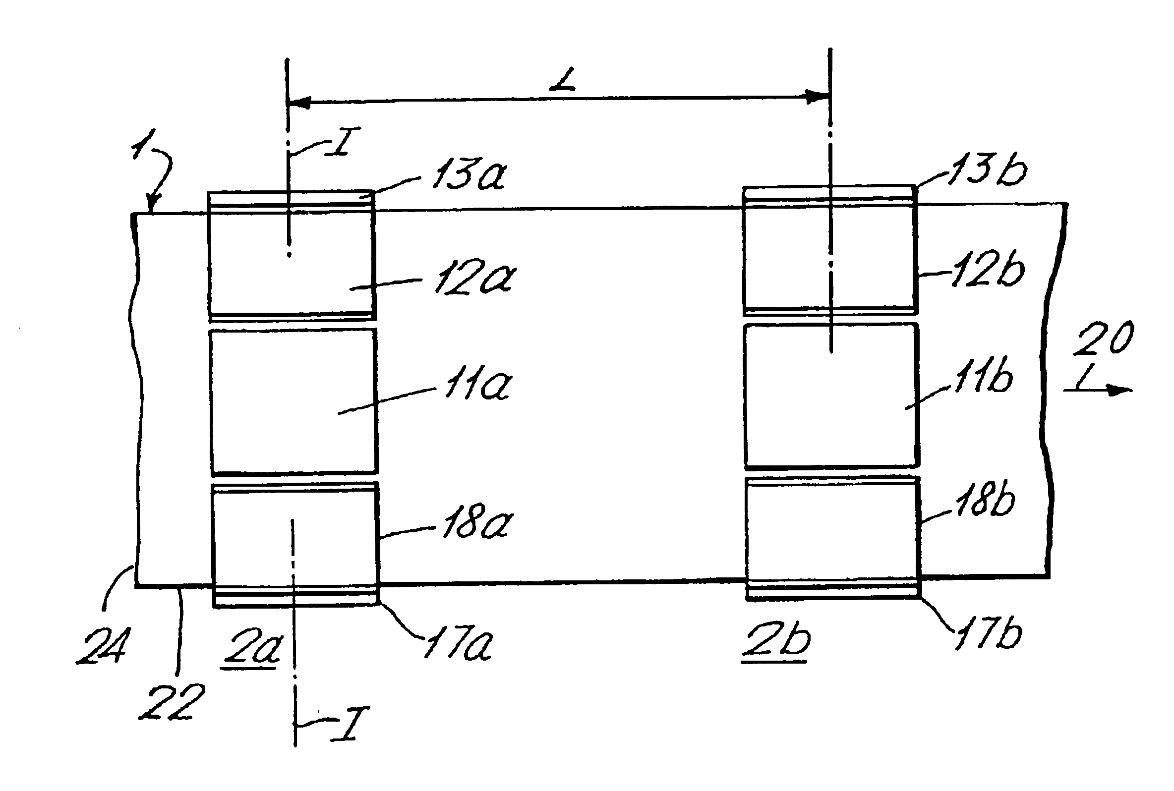
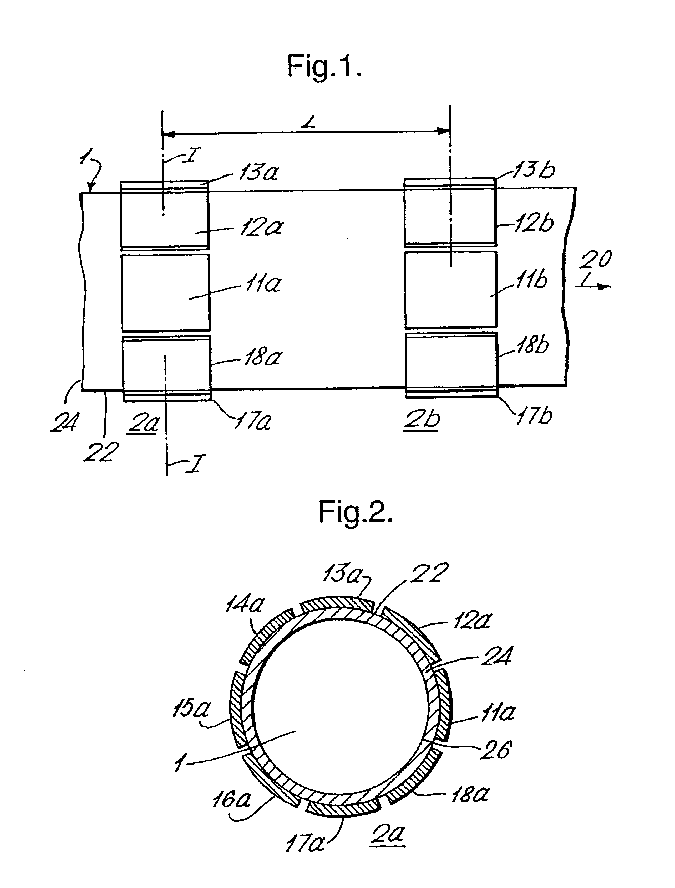
[0056]Reference is now made to FIGS. 1 and 2. The conduit 1 is provided with upstream and downstream annular capacitance sensors, 2a and 2b, separated by the distance L. Each annular capacitance sensor in this example comprises eight electrodes, 11a, . . . , 18a and 11b, . . . , 18b, which are uniformly distributed around the circumference of the conduit 1.

[0057]Normal operation of the cross-correlation capacitance meter as schematically depicted in FIGS. 1 and 2, will now be described, wherein a multi-component fluid is flowing through the conduit 1 in the direction of the arrow 20.

[0058]At first, a set of measurement capacitors is selected. In this example, a measurement capacitor is formed by a pair of single sensor electrodes, and all 8*(8−1) / 2=28 possible pairs of single sensor electrodes at the upstream sensor are selected, i.e. the pairs (11a, 12a); (11a, 13a); . . . ; (11a, 18a); (12a, 13a); . . . ; (12a, 18a); . . . ; (17a, 18a), as well as all 28 pairs of single sensor ele...


PUM

PropertyMeasurementUnit
capacitanceaaaaaaaaaa
circumferenceaaaaaaaaaa
capacitancesaaaaaaaaaa

Abstract

A method for determining a flow property of a fluid flowing through a conduit provided with a capacitance meter having an upstream and a downstream annular capacitance sensor, wherein each annular capacitance sensor having at least three sensor electrodes, which sensor electrodes are arranged around the circumference of the conduit, the method having selecting, for each annular capacitance sensor a set of measurement capacitors, wherein a measurement capacitor is formed by two measurement electrodes, and wherein a measurement electrode consists either of a single sensor electrode or of at least two interconnected sensor electrodes; measuring at several moments during a time interval a capacitance of each measurement capacitor of each annular capacitance sensor; determining cross correlations between capacitances measured during the time interval at the upstream annular capacitance sensor and capacitances measured during the time interval at the downstream annular capacitance sensor; and determining the flow property from the cross correlations.

Description

FIELD OF THE INVENTION[0001]The present invention relates to determining a property of a fluid in a conduit using a capacitance meter.BACKGROUND OF THE INVENTION[0002]Capacitance meters are used in the art to measure a dielectric property of a fluid. Often, based on one or more measurements of a dielectric property, another property of the fluid can be determined.[0003]A particular application of capacitance meters is in obtaining a pictorial representation of a property of a fluid over a cross-section of the conduit, e.g. the dielectric constant or the spatial distribution of a particular component of a multi-component fluid. In the specification the word ‘image’ is used to refer to such a pictorial representation. A multi-component fluid is a fluid comprising more than one component, for example a well fluid produced from an underground formation, which well fluid can comprise hydrocarbon oil, water, and / or natural gas.[0004]Methods that provide an image of the fluid based on capa...

Claims


Application Information

Patent Timeline
Patent Type & Authority Patents(United States)
IPC IPC(8): G01F1/56G01F1/712G01F1/704G01F1/64G01N27/22G01F1/74
CPCG01F1/64G01F1/712
Inventor HAASE, MARK CHRISTOPHERVAN DER SPEK, ALEXANDER MICHAEL
Owner SHELL OIL CO
Why Eureka
Eureka Blog
Learn More