
Optical information recording medium and information recording method and apparatus using the recording medium

a technology of information recording and information, applied in the field of optical information recording medium, can solve the problem of difficult setting of suitable recording conditions, and achieve the effect of good signal properties

Inactive Publication Date: 2005-07-05
RICOH KK
View PDF11 Cites 9 Cited by
  • Summary
  • Abstract
  • Description
  • Claims
  • Application Information

AI Technical Summary

Benefits of technology

[0009]Accordingly, an object of the present invention is to provide an optical information recording medium in which information having good signal properties can be recorded even when used for recording methods such as multi-speed recording and CAV recording in which information is recorded at different linear recording speeds.
[0010]Another object of the present invention is to provide an information recording method and apparatus in which information having good signal properties can be recorded in an optical recording medium even when changing the recording speeds.
[0024]It is preferable that the recording medium stores information, wherein the 1 signal is recorded or rewritten while the at least one of x, y and z is at a fixed value in the range thereof using the information to easily set the recording conditions, resulting in high-speed and high-precision recording.

Problems solved by technology

Therefore, in CAV recording in which linear recording speed is continuously changed as the recording point moves in a diameter direction of a recording medium, the setting of suitable recording conditions is very difficult.

Method used


Image

  • Optical information recording medium and information recording method and apparatus using the recording medium
  • Optical information recording medium and information recording method and apparatus using the recording medium
  • Optical information recording medium and information recording method and apparatus using the recording medium

Examples


example 1

[0085]A polycarbonate substrate was formed by an injection molding method. The polycarbonate substrate had a spiral groove having a track pitch of 0.74 μm, a depth of 25 nm, a width of 250 nm and a wobble period of 4.3 μm. On the polycarbonate substrate, a lower protective layer of ZnS.SiO2 having a thickness of 80 nm, a Ag4Ge1In8Sb60Te27 recording layer having a thickness of 15 nm, an upper protective layer in which a layer of ZnS.SiO2 having a thickness of 15 nm and a layer of SiC having a thickness of 5 nm were overlaid, and a reflection layer of Ag having a thickness of 140 nm were formed in this order by sputtering.

[0086]In addition, an overcoat layer was formed on the reflection layer by coating an ultraviolet crosslinking resin by a spin coating method. Thus a phase-change single plate disk, which has a DVD-ROM reproduction compatibility, was formed. Another polycarbonate substrate (i.e., a second polycarbonate substrate) was adhered on the overcoat layer of the thus prepared...


PUM

PropertyMeasurementUnit
radiusaaaaaaaaaa
reflectanceaaaaaaaaaa

Abstract

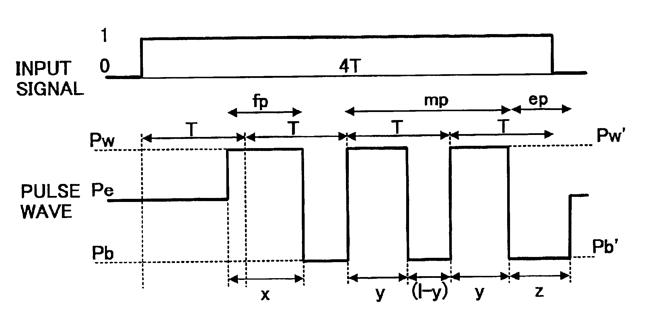
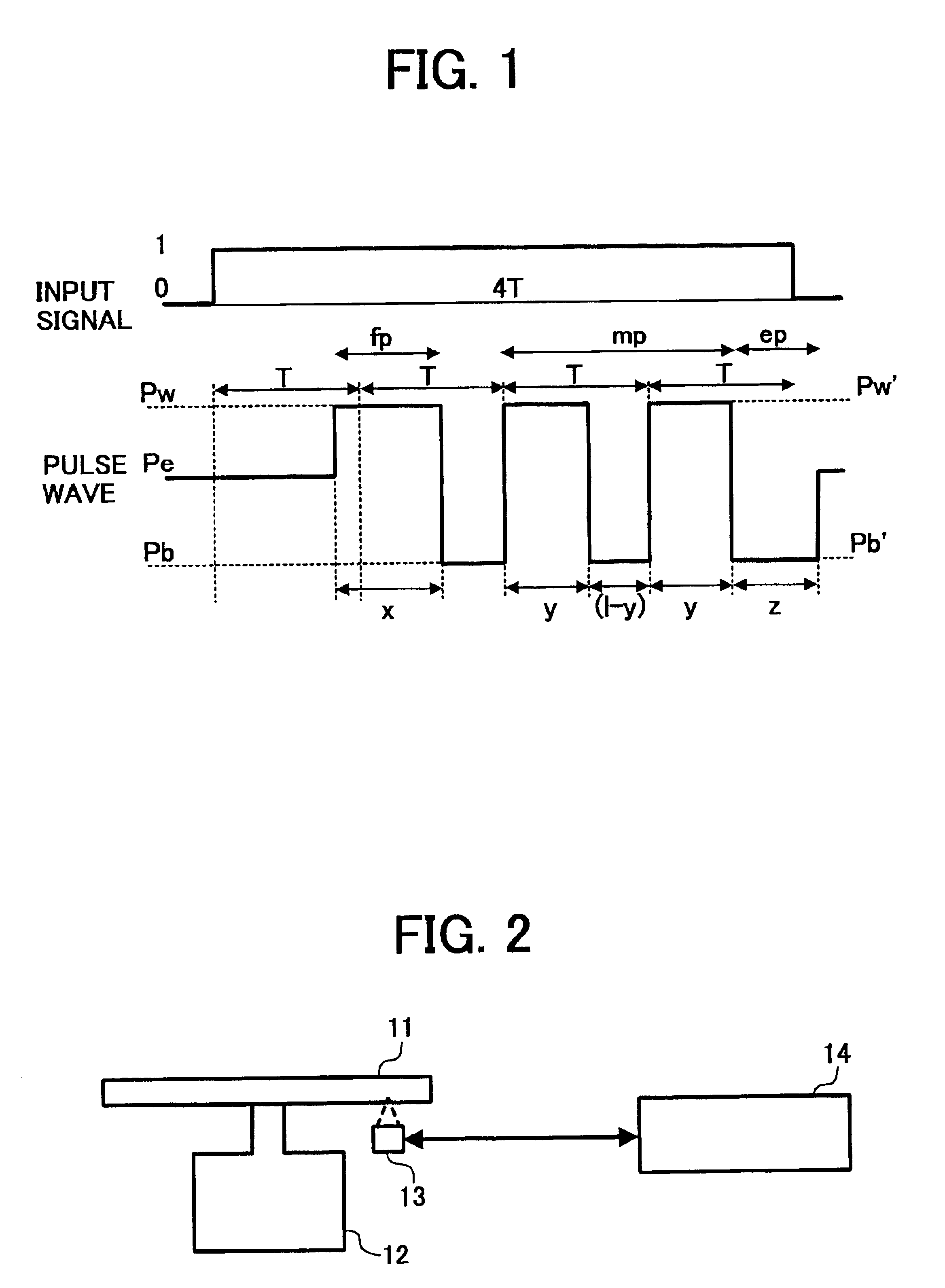
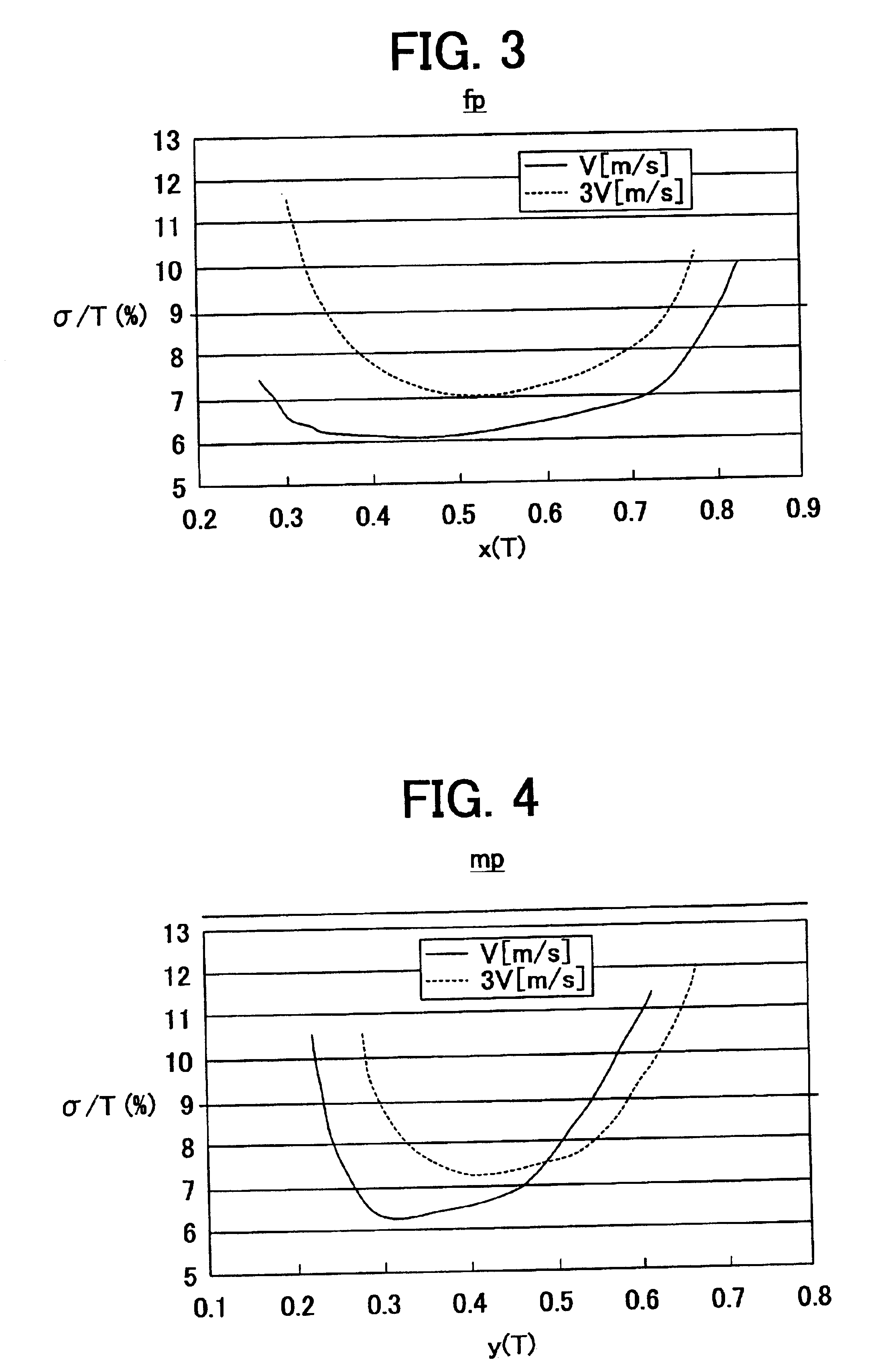
An optical information recording method including: irradiating a recording medium with laser light, wherein 0 signals having width nT are recorded or rewritten using continuous laser light having a power level Pe, and 1 signals having width nT are recorded or rewritten using a light pulse train having a first pulse portion fp having power Pw and width xT (T: clock time), a multi-pulse portion mp in which a number (n−n′) of high level pulses each having power Pw′ and width yT, and, if (n−n′)>1, a low level pulse which has power Pb and width (1−y)T are applied, and an end pulse portion ep having power Pb′ and width zT, wherein n and n′ are a positive integer (n>n′), and wherein each of Pw and Pw′ is greater than Pe, Pe is greater than each of Pb and Pb′, and at least one of x, y and z is in a range as follows: 0.35≦x≦0.75, 0.30≦y≦0.55, 0.35≦z≦0.70.

Description

BACKGROUND OF THE INVENTION[0001]1. Field of the Invention[0002]The present invention relates to an optical information recording medium, and more particularly to a phase-change optical information recording medium in which information is recorded, reproduced and rewritten by changing an optical property of a material in the recording layer thereof by irradiating the recording layer with a laser light beam. In addition, the present invention also relates to an information recording method and apparatus using the optical information recording medium.[0003]2. Discussion of the Related Art[0004]Various optical information recording media capable of recording and reproducing information upon irradiation of laser light thereto have been developed and used. Specific examples of such optical information recording media include CD-Rs and DVD-Rs, in which information can be written once, and CD-RWs, DVD-RWs, DVD-RAMs, MDs and MO disks, in which information can be rewritten. These optical inf...

Claims


Application Information

Patent Timeline
Patent Type & Authority Patents(United States)
IPC IPC(8): G11B7/243G11B7/125G11B7/0045G11B7/24G11B7/00G11B7/253G11B7/2534G11B7/254G11B7/2542G11B7/257G11B7/2578G11B7/258
CPCG11B7/0062G11B7/243G11B7/2534G11B7/2542G11B7/256G11B7/257G11B7/2578G11B7/258G11B2007/24314G11B2007/24316G11B2007/25713G11B2007/25715G11B2007/25716
Inventor NARUMI, SHINYAYAMADA, KATSUYUKIITO, KAZUNORIYUZURIHARA, HAJIMEONAGI, NOBUAKI
Owner RICOH KK
Learn More