
Apparatus and methods for cleaning and/or processing delicate parts

a technology for delicate parts and apparatus, applied in the direction of mechanical vibration separation, instruments, energy-based chemical/physical/physico-chemical processes, etc., can solve the problems of easy damage to fragile parts, extremely small features of semiconductor wafers, etc., and achieve the effect of reducing damage to delicate parts

Inactive Publication Date: 2005-07-05
PUSKAS WILLIAM L
View PDF103 Cites 11 Cited by
  • Summary
  • Abstract
  • Description
  • Claims
  • Application Information

AI Technical Summary

Benefits of technology

[0062]The present invention concerns the applied uses of ultrasound energy, and in particular the application and control of ultrasonics to clean and process delicate parts, e.g., semiconductor wafers, within a liquid. Generally, in accord with the invention, one or more ultrasonic generators drive one or more ultrasonic transducers, or arrays of transducers, coupled to a liquid to clean and / or process the delicate part. The liquid is preferably held within a tank; and the transducers mount on or within the tank to impart ultrasound into the liquid. In this context, the invention is particularly directed to one or more of the following aspects and advantages:
[0111]In yet another aspect, the invention reduces or eliminates low frequency beat resonances created by multiple generators by synchronizing the sweep rates (both in magnitude and in phase) so that there is zero frequency difference between the signals coming out of multiple generators. In one aspect, the synchronization of sweep rate magnitude and phase is accomplished by sending a timing signal from one generator to each of the other generators. In another aspect, a master FM signal is generated that is sent to each “slave” power module, which amplifies the master FM signal for delivery to the transducers. At times, the master and slave aspect of the invention also provides advantages in eliminating or reducing the beat frequency created by multiple generators driving a single tank.

Problems solved by technology

By way of example, one delicate part is a semiconductor wafer which has extremely small features and which is easily damaged by cavitation implosion.

Method used


Image

  • Apparatus and methods for cleaning and/or processing delicate parts
  • Apparatus and methods for cleaning and/or processing delicate parts
  • Apparatus and methods for cleaning and/or processing delicate parts

Examples


Embodiment Construction

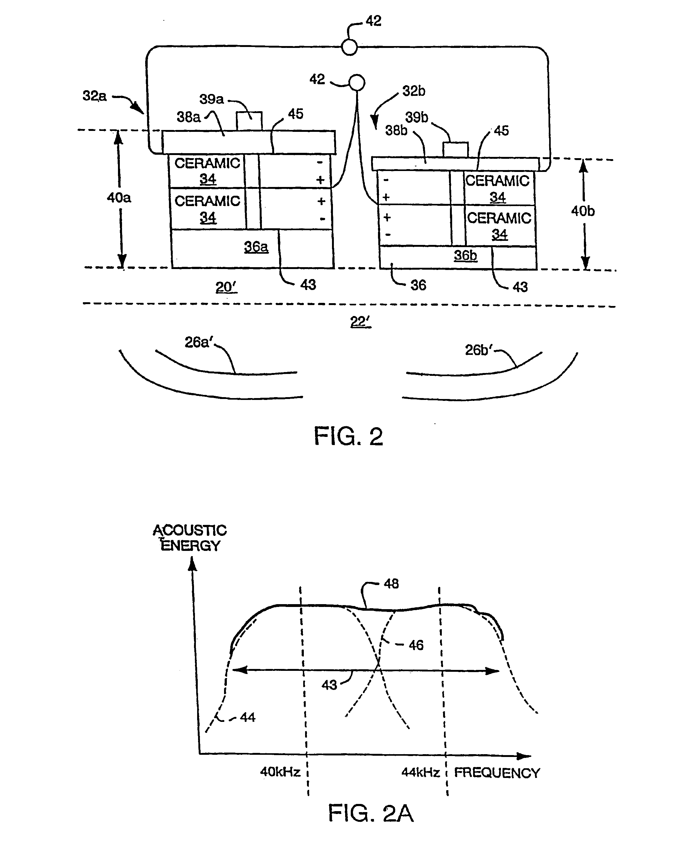
[0139]FIGS. 1 and 1A show schematic side and top views, respectively, of an ultrasound processing system 10 constructed according to the invention. An ultrasonic generator 12 electrically connects, via electrical paths 14a, 14b, to an ultrasound transducer 16 to drive the transducer 16 at ultrasound frequencies above about 18 khz, and usually between 40 khz and 350 khz. Though not required, the transducer 16 is shown in FIG. 1 as an array of transducer elements 18. Typically, such elements 18 are made from ceramic, piezoelectric, or magnetostrictive materials which expand and contract with applied voltages or current to create ultrasound. The transducer 16 is mounted to the bottom, to the sides, or within the ultrasound treatment tank 20 through conventional methods, such as known to those skilled in the art and as described above. A liquid 22 fills the tank to a level sufficient to cover the delicate part 24 to be processed and / or cleaned. In operation, the generator 12 drives the ...


PUM


Abstract

The invention utilizes harmonics of certain clamped ultrasound transducers to generate ultrasound within the liquid of an ultrasonic tank and in a frequency range of between about 100 khz to 350 khz (i.e., “microsonic” frequencies). The application of microsonic frequencies to liquid preferably occurs simultaneously with a sweeping of the microsonic frequency within the transducer's harmonic bandwidth to reduce or eliminate (a) standing waves within the liquid, (b) other resonances, (c) high energy cavitation implosion, and (d) non-uniform sound fields, each of which is undesirable for cleaning and / or processing of semiconductor wafers and other delicate parts. The invention can also drive ultrasonic transducers such that the frequency of applied energy has a sweep rate within the ultrasonic bandwidth of the transducers; and that sweep rate is also varied so that the sweep rate is substantially non-constant during operation. This reduces or eliminates resonances which are created by transducers operating with a single sweep rate. An ultrasound generator of the invention sometimes utilizes amplitude modulation (AM), and the AM frequency is swept over time so as to reduce resonances. AM control is preferably provided by selecting a portion of the rectified power line frequency. In applications which utilize multiple generators, multiple transducers, and one or more tanks, simultaneously, the invention synchronizes the operation of the generators to a common FM signal to reduce beat frequencies between generators. Each such generator can also be adjusted, through AM, to control the process characteristics within the associated tank. Two or more transducers are sometimes used by the invention, in combination, to broaden the overall bandwidth of acoustical energy applied to the liquid around the primary frequency or one of the harmonics. The bandwidths of the transducers are made to overlap such that an attached generator can drive the transducers, in combination, to deliver ultrasound to the liquid in a broader bandwidth. In a single chamber ultrasound system, two or more generators, each operating or optimized to generate a different range of frequencies, are connected to a multiplexer; and the desired frequency range is selected, and hence the right generator, according to the cavitation implosion energy that is desired within the tank chemistry.

Description

RELATED APPLICATIONS[0001]This application is a Continuation Application of Divisional application Ser. No. 09 / 678,576, filed Oct. 3, 2000 now U.S. Pat. No. 6,433,460, which is a divisional application of Continuation-in-Part application Ser. No. 09 / 066,158, filed Apr. 24, 1998, now U.S. Pat. No. 6,181,051 entitled “Apparatus And Methods For Cleaning And / Or Processing Delicate Parts”, which is a continuation of U.S. patent application Ser. No. 08 / 718,945 filed on Sep. 24, 1996, now U.S. Pat. No. 5,834,871, entitled “Apparatus And Methods For Cleaning Md / Or Processing Delicate Parts”, and U.S. Provisional Patent Application Ser. No. 60 / 023,150, filed on Aug. 5, 1996, each of which is expressly incorporated herein by reference.[0002]The specification attached hereto corresponds to the specification existing in the parent application Ser. No. 09 / 678,576, including amendments to correct the specification.FIELD OF THE INVENTION[0003]The invention relates to systems and methods for cleani...

Claims


Application Information

Patent Timeline
IPC IPC(8): B01J19/10B06B1/06B06B1/02G10K11/00
CPCB01J19/10B06B1/0276B06B1/0618B06B1/0622G10K11/004G10K11/006B06B2201/71
Inventor PUSKAS, WILLIAM L.
Owner PUSKAS WILLIAM L
Learn More