
Process for selectively etching dielectric layers

a dielectric layer and selective etching technology, applied in the direction of basic electric elements, electric apparatus, semiconductor/solid-state device manufacturing, etc., to achieve the effect of reducing cross-talk and coupling, high dielectric constant, and reducing structure capacitan

Inactive Publication Date: 2005-06-14
APPLIED MATERIALS INC
View PDF26 Cites 27 Cited by
  • Summary
  • Abstract
  • Description
  • Claims
  • Application Information

AI Technical Summary

Benefits of technology

[0021]One advantage of the present invention is that a C,H-doped silicon oxide dielectric layer can be preferentially etched relative to an undoped silicon oxide dielectric layer and an F-doped silicon oxide dielectric layer.

Problems solved by technology

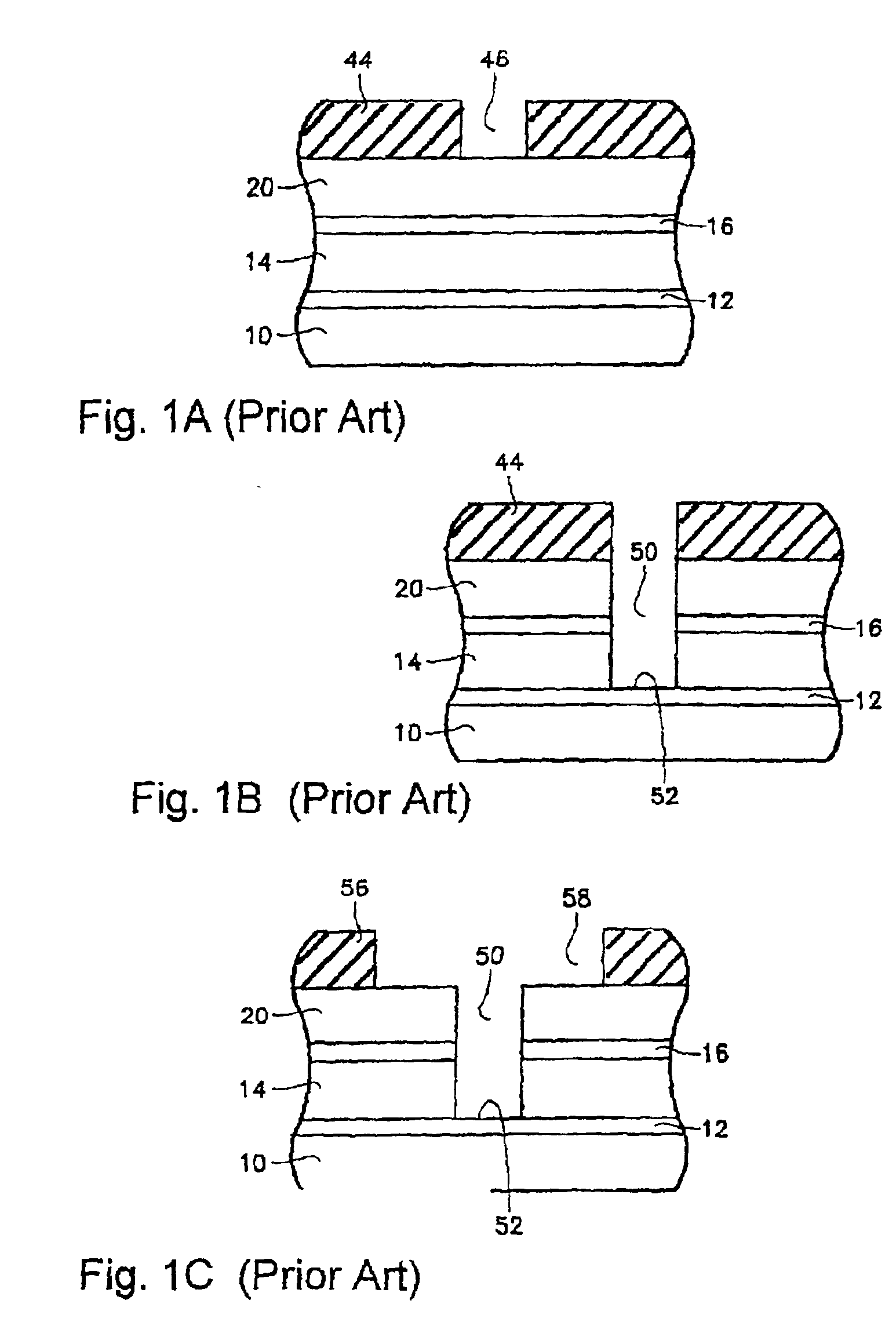
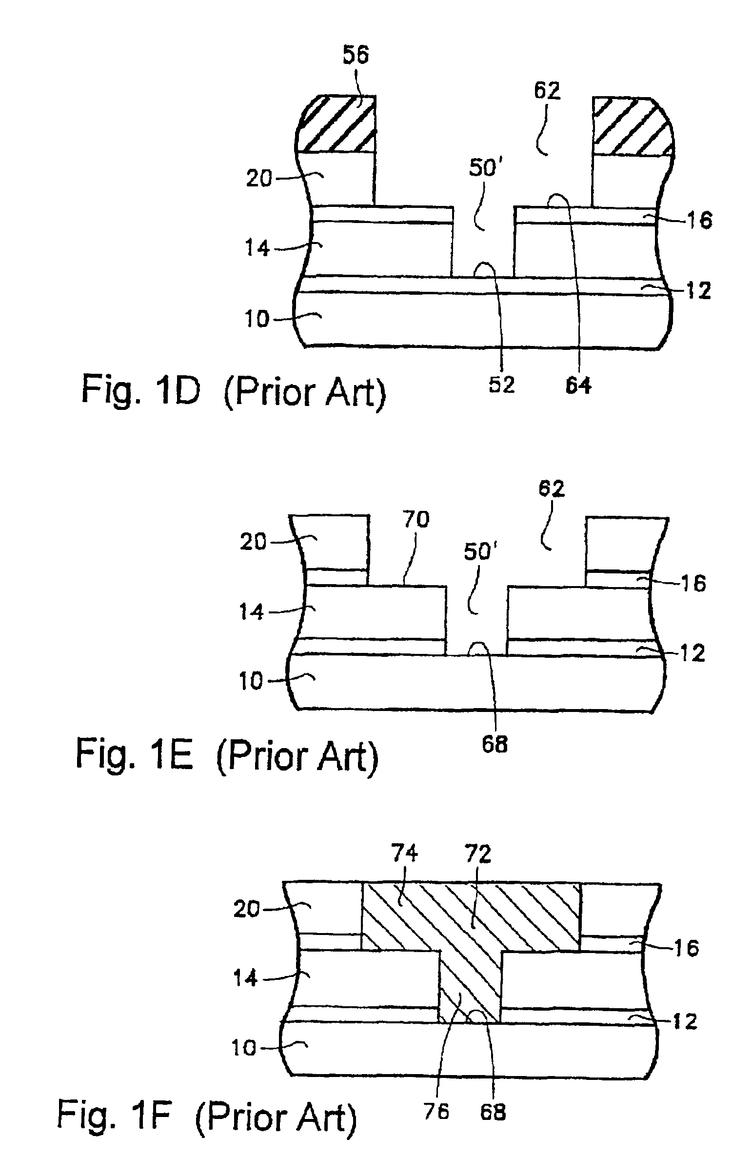
Unfortunately, the materials that are typically used in connection with the stop layers 12, 16 (e.g., silicon nitride) are relatively high-dielectric-constant k materials.

Method used


Image

  • Process for selectively etching dielectric layers
  • Process for selectively etching dielectric layers
  • Process for selectively etching dielectric layers

Examples


Embodiment Construction

[0027]As a preface to the detailed description, it should be noted that, all percentages (%) listed for gas constituents are % by volume, and all ratios listed for gas constituents are volume ratios.

[0028]The term “selectivity” is used to refer to a) a ratio of etch rates of two or more materials and b) a condition achieved during etch when the etch rate of one material is increased in comparison with another material.

[0029]The present invention now will be described more fully hereinafter with reference to the Figures, in which exemplary embodiments of the present invention are shown. This invention, however, may be embodied in different forms and should not be construed as limited to the embodiments set forth herein.

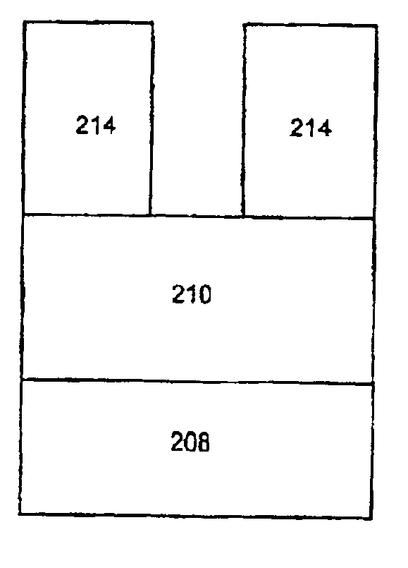
[0030]A process in accordance with an embodiment of the invention will now be discussed in connection with FIGS. 2A and 2B. Referring to FIG. 2A, a structure is illustrated which includes a lower dielectric layer 208, an upper dielectric layer 210 and a patterned maski...


PUM


Abstract

A method is provided for etching a dielectric structure. The dielectric structure comprises: (a) a layer of undoped silicon oxide or F-doped silicon oxide; and (b) a layer of C,H-doped silicon oxide. The dielectric structure is etched in a plasma-etching step, which plasma-etching step is conducted using a plasma source gas that comprises nitrogen atoms and fluorine atoms. As one example, the plasma source gas can comprise a gaseous species that comprises one or more nitrogen atoms and one or more fluorine atoms (e.g., NF3). As another example, the plasma source gas can comprise (a) a gaseous species that comprises one or more nitrogen atoms (e.g., N2) and (b) a gaseous species that comprises one or more fluorine atoms (e.g., a fluorocarbon gas such as CF4). In this etching step, the layer of C,H-doped silicon oxide is preferentially etched relative to the layer of undoped silicon oxide or F-doped silicon oxide. The method of the present invention is applicable, for example, to dual damascene structures.

Description

BACKGROUND OF THE INVENTION[0001]The present invention relates to processes for selectively etching dielectric layers, for example, in the context of a dual damascene process.[0002]The technology of fabricating semiconductor integrated circuits continues to advance in the number of transistors, diodes, capacitors and / or other electronic devices that can be fabricated on a single integrated circuit chip. This increasing level of integration is being accomplished in large part by decreasing minimum feature sizes.[0003]Advanced integrated circuits contain multiple interconnect layers separated from the semiconductor substrate and from each other by respective dielectric layers. For instance, logic circuitry, such as that found in microprocessors, requires several interconnect layers with intervening dielectric layers. A horizontal interconnect layer is formed over one dielectric layer and then covered by another dielectric layer. Small contact or via holes need to be etched through eac...

Claims


Application Information

Patent Timeline
Patent Type & Authority Patents(United States)
IPC IPC(8): H01L21/02H01L21/70H01L21/768H01L21/311H01L21/316
CPCH01L21/31116H01L21/76835H01L21/76808H01L21/31629H01L21/31633H01L21/02126H01L21/02274H01L21/311
Inventor HSIEH, CHANG-LINYUAN, JIECHEN, HUIPANAGOPOULOS, THEODOROSYE, YAN
Owner APPLIED MATERIALS INC
Learn More