Connector
a technology of connectors and connectors, applied in the direction of connection contact material, coupling device connection, coupling protective earth/shielding arrangement, etc., can solve the problems of slow computer processing speed, adverse influence on signal transmission speed and stability, and data transmission speed reduction, etc., to achieve the effect of more rapid and stable transmission of signals through the connectors
- Summary
- Abstract
- Description
- Claims
- Application Information
AI Technical Summary
Benefits of technology
Problems solved by technology
Method used
Image
Examples
first embodiment
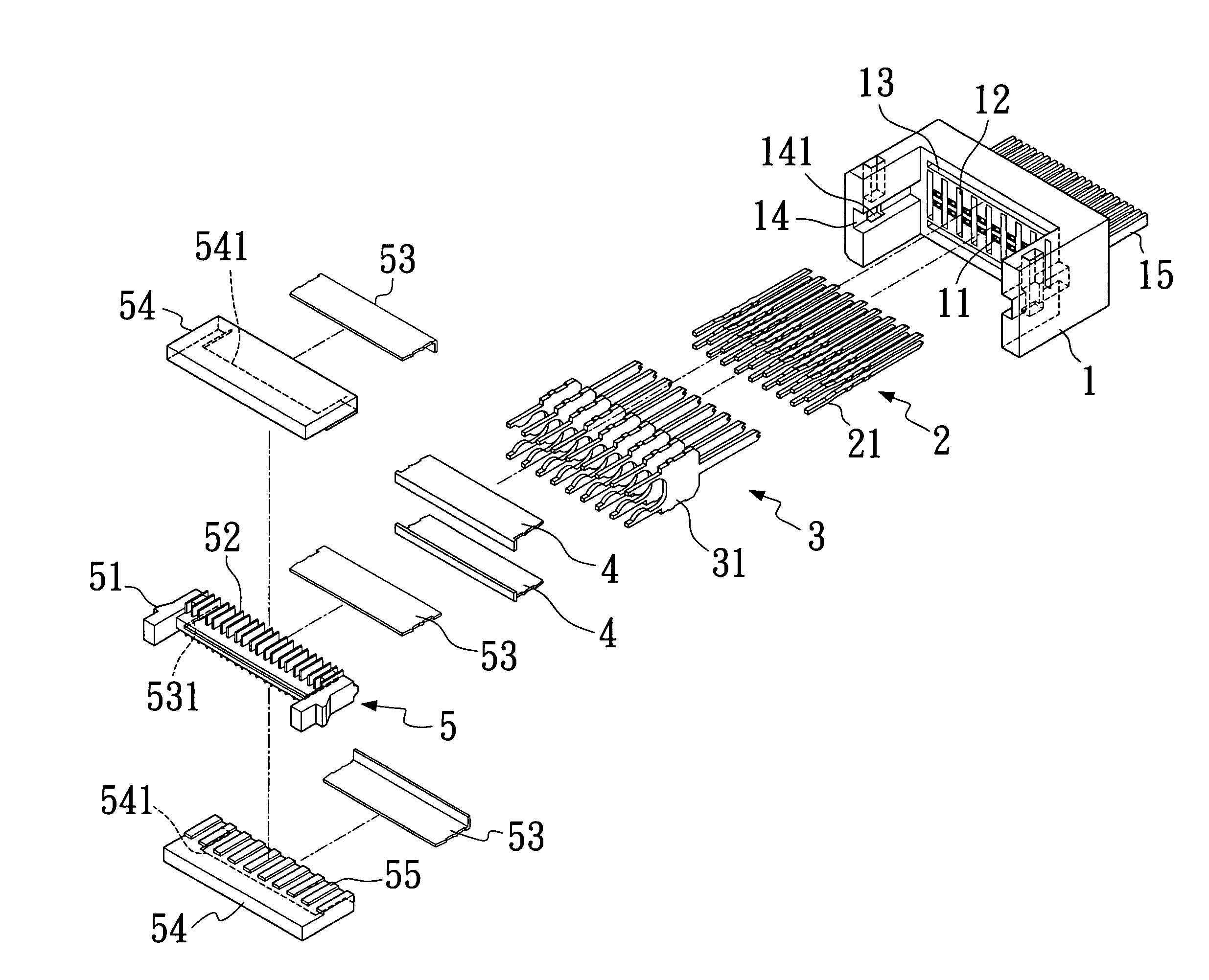
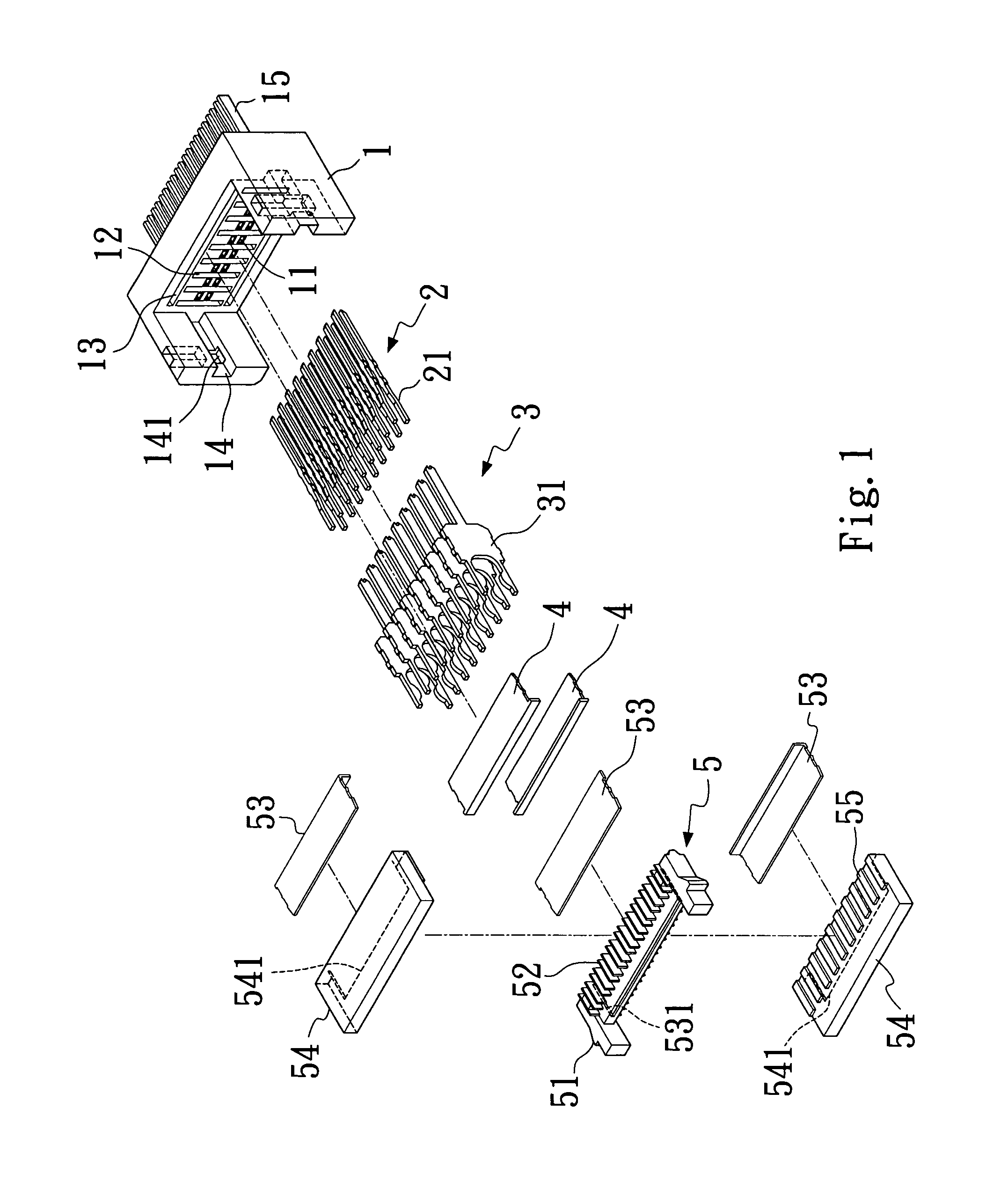
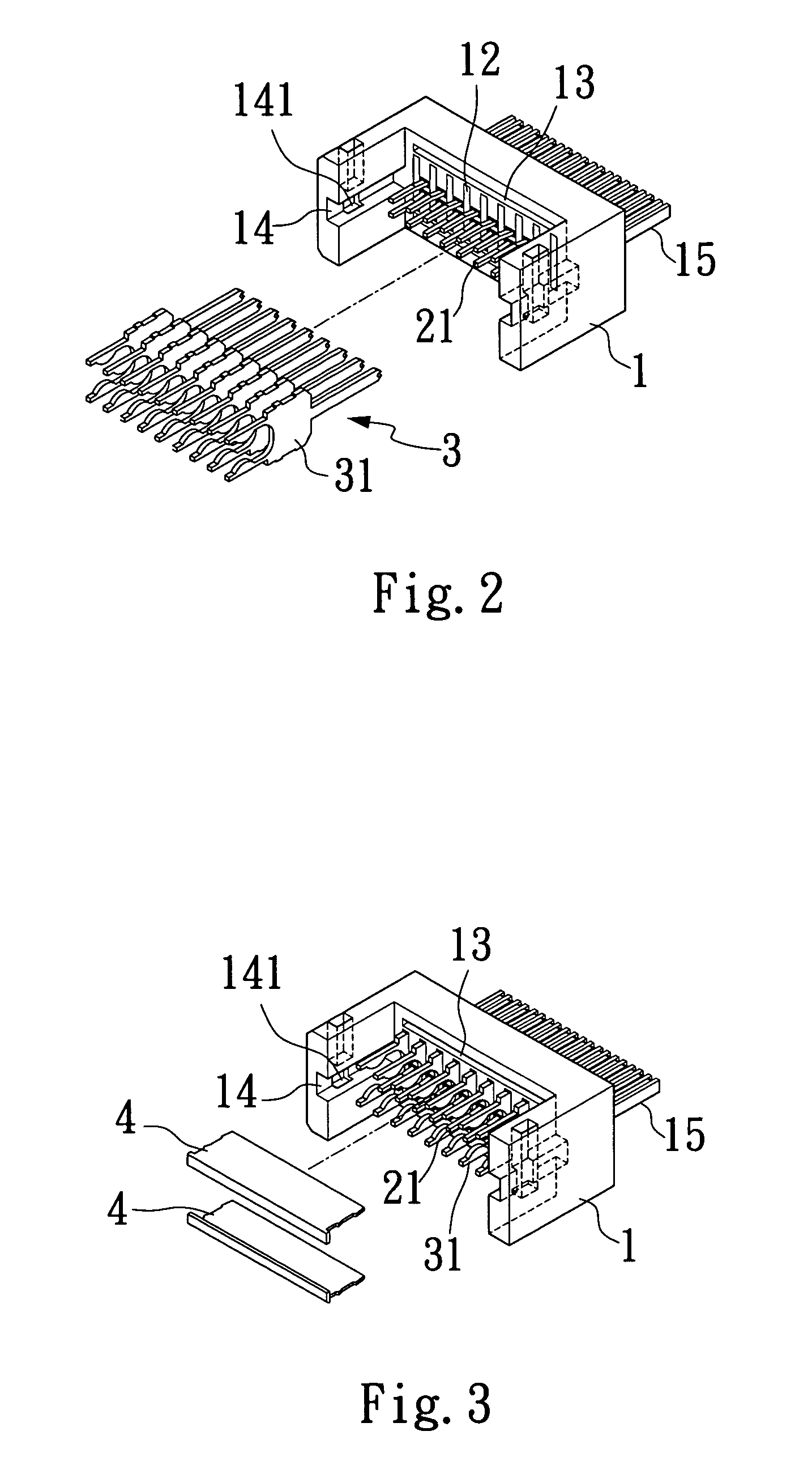
[0037]Please refer to FIG. 1 that is an exploded perspective view of a connector according to the present invention, and to FIGS. 2 and 3 that are partially assembled perspective views of the connector of FIG. 1. As shown, the connector mainly includes a plastic core 1, a set of terminals 2, a set of first isolating plates 3, two first conductive plates 4, and an insertion element 5.
[0038]The plastic core 1 is provided on an inner central portion at upper and lower sides thereof with upper and lower receiving slots 13, and at an area of the inner central portion between the upper and lower receiving slots 13 with a plurality of alternately arranged terminal slots 11 and isolating plate slots 12. The terminal slots 11 are divided into an upper and a lower row. The plastic core 1 is also provided at each of two lateral inner sides with a slide way 14, in which a retaining slot 141 is provided at a predetermined position. A connecting head 15 is externally provided at a front end of th...
second embodiment
[0053]FIG. 13 is a cross sectional view taken along line C–C′ of FIG. 12. Please refer to FIG. 13. As shown, in the fully assembled connector according to the present invention, the first isolating plates 861 together form a plurality of isolated cells that separate and isolate individual terminals 851 from one another, and the two first conductive plates 87 eliminate the interferences between the terminals 851 and from external environments, so that signals may be transmitted via the connector more quickly and stably. Moreover, with the engagement of the central slits 871 on the first conductive plates 87 with the central ribs 841 in the upper and lower receiving slots 84 on the plastic core 8, the central slits 871 on the second conductive plate 87 with the central rib 882 in the central receiving slot 881 of the insertion element 88, and the central slits 871 on the third conductive plates 87 with the central ribs 931 in transverse recesses 93 of the outer covers 91, the first, t...
third embodiment
[0060]The outer covers 112 are located at upper and lower sides of the insertion element 109 to enclose the insertion element 109 in the plastic core 10. Each of the outer covers 112 is provided at an inner side with a plurality of isolating ribs 113 corresponding to and covering spaces between the second isolating plates 111 on the insertion element 109. Each of the outer covers 112 is also internally provided at a central position with a transverse recess 114 having a plurality of equally spaced ribs 1141, into which a third conductive plate 108 having a plurality of equally spaced slits 1081 is received with the slits 1081 engaged with the ribs 1141 and thereby firmly hold the third conductive plate 108 in the transverse recess 114. The third conductive plates 108 received in the two outer covers 112 are in contact with the first conductive plates 108 received in the plastic core 10. Finally, terminals 1151 of two signal cables 115 are separately connected to the terminals 1061 o...
PUM
 Abstract
Description
Claims
Application Information
 - R&D
- Intellectual Property
- Life Sciences
- Materials
- Tech Scout
- Unparalleled Data Quality
- Higher Quality Content
- 60% Fewer Hallucinations
Browse by: Latest US Patents, China's latest patents, Technical Efficacy Thesaurus, Application Domain, Technology Topic, Popular Technical Reports.
© 2025 PatSnap. All rights reserved.Legal|Privacy policy|Modern Slavery Act Transparency Statement|Sitemap|About US| Contact US: help@patsnap.com


