
Electric discharge machine with reactive force compensated by jump locus adjustment

a technology of reactive force and electric discharge machine, which is applied in the direction of electric circuits, manufacturing tools, metal-working apparatuses, etc., can solve the problems of deteriorating final machining accuracy of workpieces, damage to electric and part drives, and increased machining time, so as to prevent machining accuracy from deteriorating, reduce the time of jumping motion, and enhance the effect of electric discharge machining

Inactive Publication Date: 2005-05-31
MITSUBISHI ELECTRIC CORP +1
View PDF10 Cites 2 Cited by
  • Summary
  • Abstract
  • Description
  • Claims
  • Application Information

AI Technical Summary

Benefits of technology

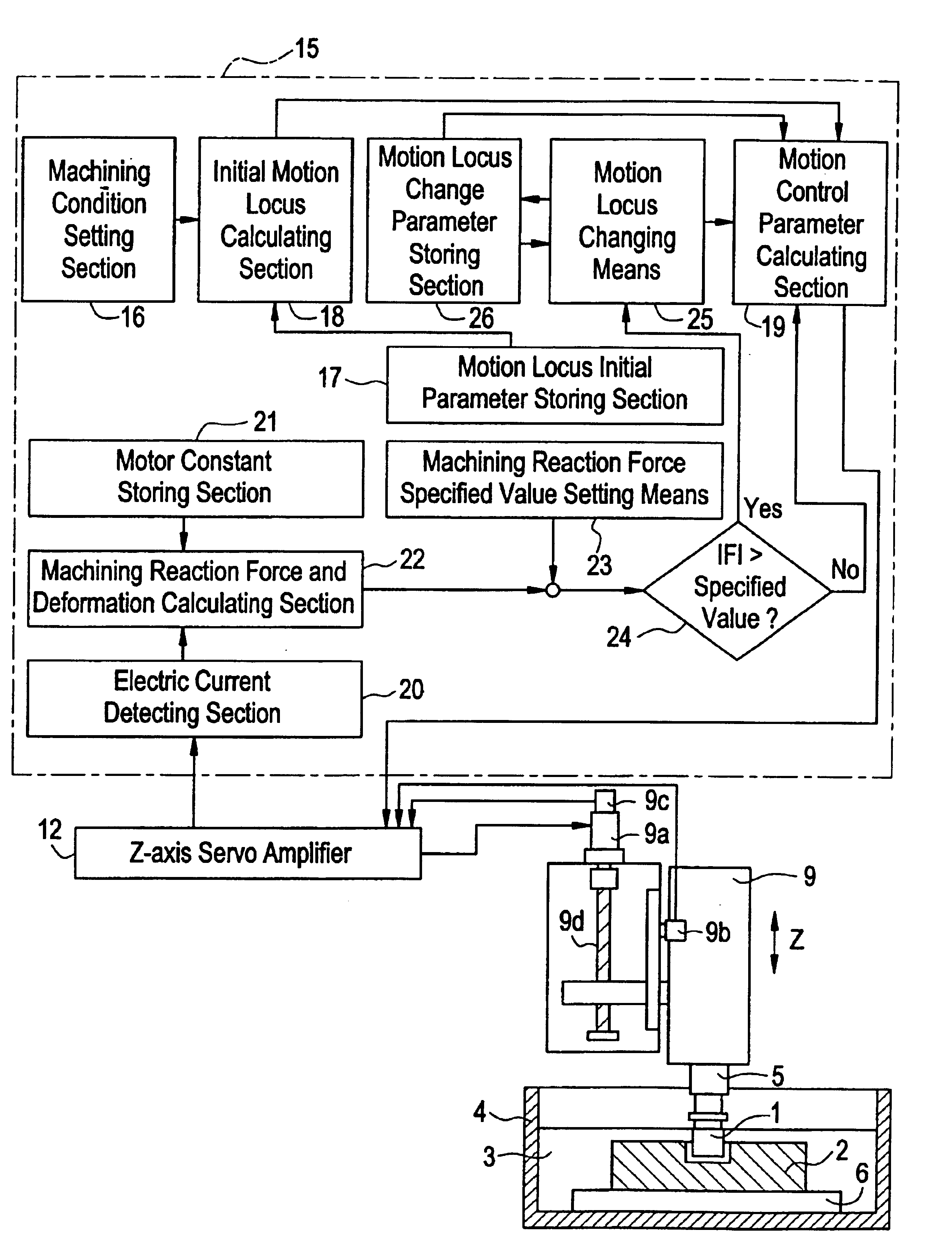
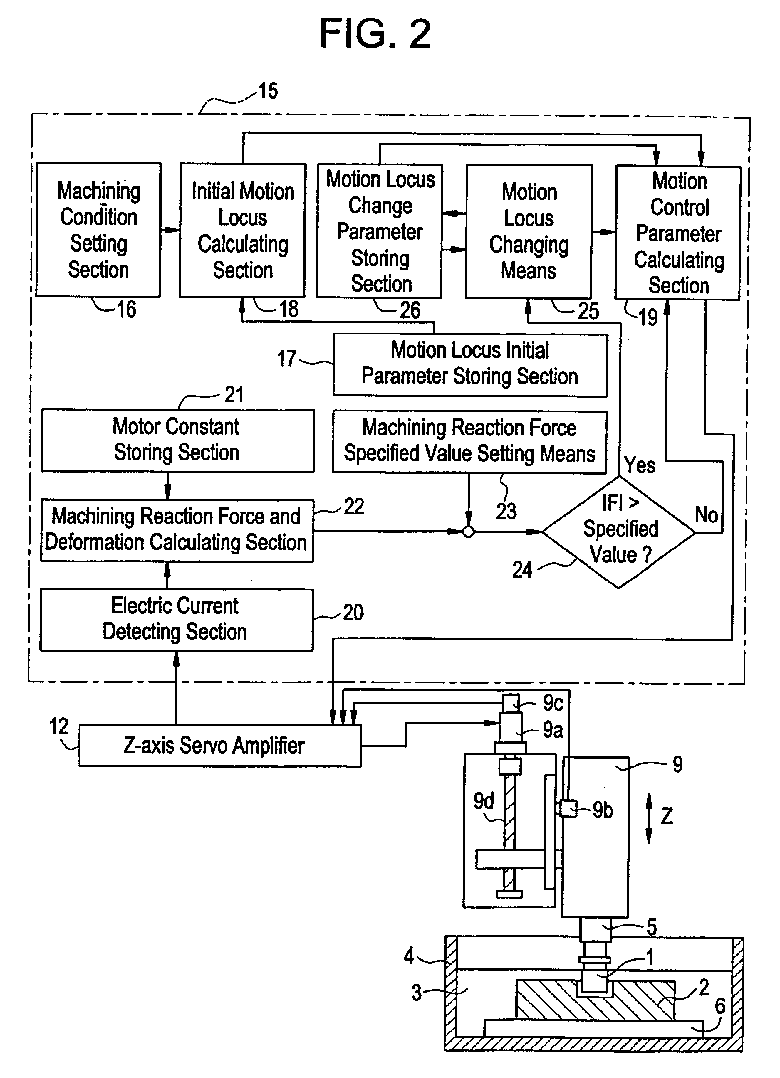
The present invention provides an electric discharge machine that can reduce the reaction force of machining and the jumping motion of the electrode, which can prevent damage to the primary driving shaft and improve the accuracy of machining. The machine includes a machining reaction force detecting means, a machining reaction force specified value setting means, a machining reaction force comparing means, and a motion locus changing means. The machine also detects and reduces deformation of the machine body, and changes the specified value of machining stress based on the machining area and condition. The motion locus changing means changes the locus of the jumping motion to reduce the machining stress. The invention aims to enhance the efficiency and productivity of the electric discharge machine.

Problems solved by technology

At the worst, the electrode and parts to drive the primary shaft are damaged.
Further, since deformation of the entire primary shaft section to support the electrode is increased in proportion to the intensity of the reaction force caused in the process of machining, the final machining accuracy of the workpiece is deteriorated.
Accordingly, the entire machining time is increased and the productivity of electric discharge machining is decreased, which causes a problem.
Further, the following problems may be encountered.
By this vibration, the machining accuracy is deteriorated and further the machining time is increased, which deteriorates the productivity of electric discharge machining.

Method used


Image

  • Electric discharge machine with reactive force compensated by jump locus adjustment
  • Electric discharge machine with reactive force compensated by jump locus adjustment
  • Electric discharge machine with reactive force compensated by jump locus adjustment

Examples


Embodiment Construction

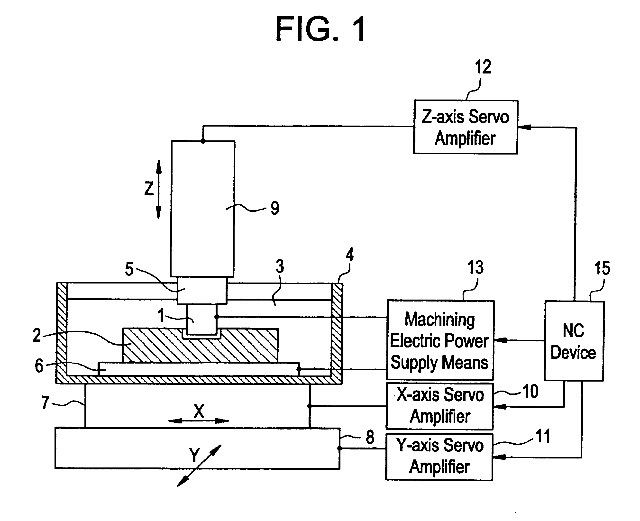
[0032]FIG. 1 is an arrangement view showing an electric discharge machine of an embodiment of the present invention. In the view, reference numeral 1 is an electrode, reference numeral 2 is a workpiece, reference numeral 3 is a machining solution, reference numeral 4 is a machining tank, reference numeral 5 is an electrode holding jig, reference numeral 6 is a surface plate for fixing the workpiece 2, reference numerals 7 and 8 are respectively X-axis and Y-axis for relatively moving the electrode 1 and the workpiece 2 on X-Y plane, reference numeral 9 is Z-axis which is a primary axis for relatively moving the electrode 1 and the workpiece 2 in direction Z, reference numerals 10, 11 and 12 are respectively X-axis servo amplifier, Y-axis servo amplifier and Z-axis servo amplifier for driving and controlling servo motors not shown to drive X-axis, Y-axis and Z-axis, reference numeral 13 is a machining electric power supply means, and reference numeral 15 is an NC device.

[0033]The mac...


PUM

PropertyMeasurementUnit
areaaaaaaaaaaa
distanceaaaaaaaaaa
relative speedaaaaaaaaaa

Abstract

In an electric discharge machine, wherein electric power is supplied between an electrode and a workpiece to machine the workpiece, a jumping motion is performed to temporarily increase a distance between the electrode and the workpiece. The electric discharge machine includes a detector for detecting a machining reaction force; a setting unit for setting a specified value of the machining reaction force; a comparator for comparing a detected value of the machining reaction force with a specified value of the machining reaction force; and a changing unit for changing a locus of the jumping motion so that the machining reaction force can be reduced if the comparator finds that the detected value of the machining reaction force is greater than the specified value of the machining reaction force.

Description

TECHNICAL FIELD[0001]The present invention relates to improvements in an electric discharge machine to conduct machining on a workpiece by generating electric discharge between an electrode and the workpiece in a machining solution. More particularly, the present invention relates to improvements in an electric discharge machine in which a reaction force caused in machining when a distance between the electrodes is changed can be suppressed to a value not more than a specified value.BACKGROUND ART[0002]FIG. 4 is an arrangement view showing a conventional electric discharge machine. In the view, reference numeral 1 is an electrode, reference numeral 2 is a workpiece, reference numeral 3 is a machining solution, reference numeral 4 is a machining tank, reference numeral 5 is an electrode holding jig, reference numeral 6 is a surface plate for fixing the workpiece 2, reference numerals 7 and 8 are respectively X-axis and Y-axis for relatively moving the electrode 1 and the workpiece 2 ...

Claims


Application Information

Patent Timeline
Patent Type & Authority Patents(United States)
IPC IPC(8): B23H7/00B23H1/02B23H7/18B23H7/20
CPCB23H1/02B23H7/20B23H7/18B23H11/00
Inventor MOHRI, NAOTAKESAITOH, NAGAOAKUNE, MITSUAKIOGAWA, HAJIMENAKAGAWA, TAKAYUKIIMAI, YOSHIHITO
Owner MITSUBISHI ELECTRIC CORP
Learn More