Keel cooler with fluid flow diverter
- Summary
- Abstract
- Description
- Claims
- Application Information
AI Technical Summary
Benefits of technology
Problems solved by technology
Method used
Image
Examples
Embodiment Construction
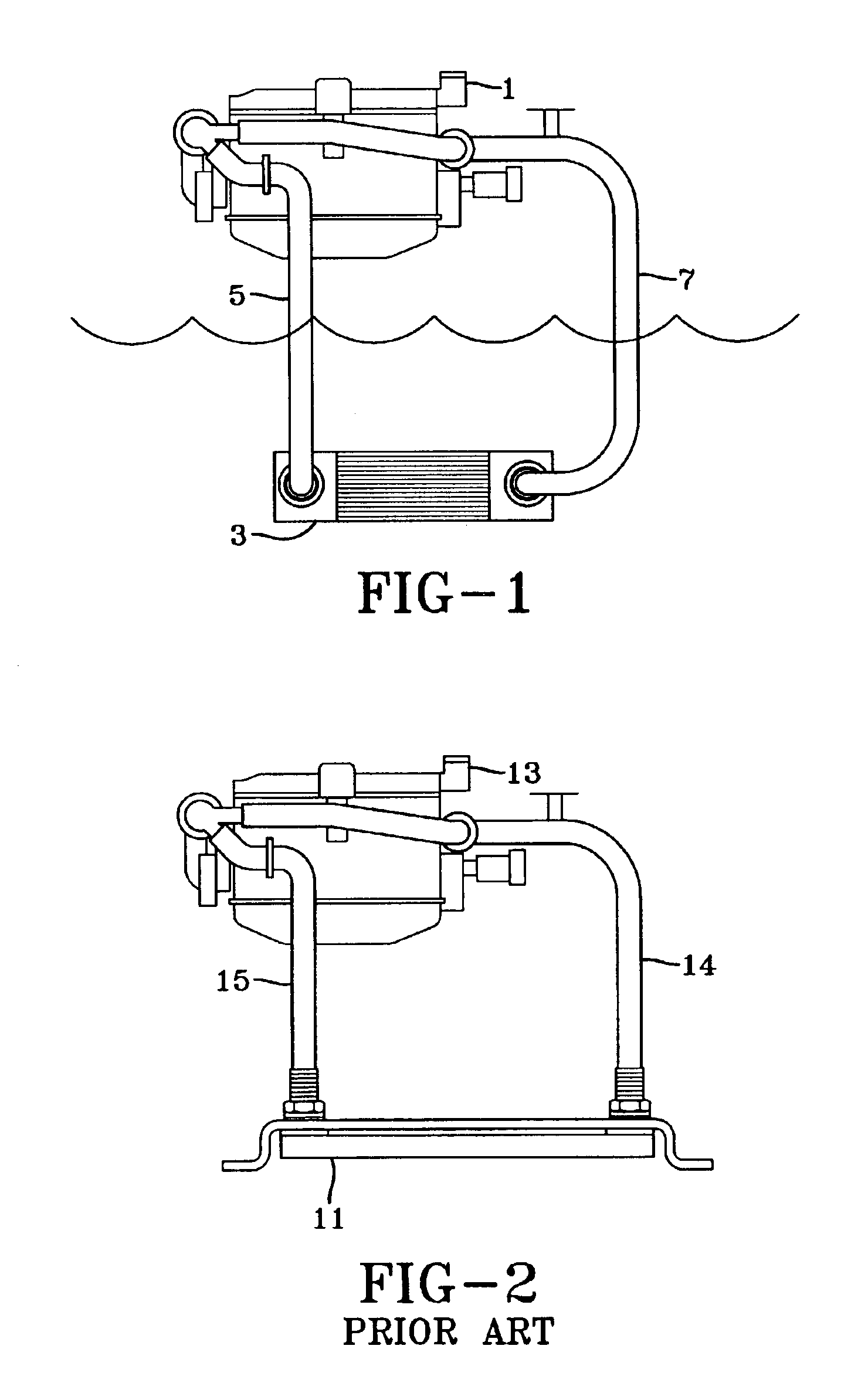
[0064]The fundamental components of a heat exchanger system for a water going vessel are shown in FIG. 1. The system includes a heat source 1, a heat exchanger 3, a pipe 5 for conveying the hot coolant from heat source 1 to heat exchanger 3, and a pipe 7 for conveying cooled coolant from heat exchanger 3 to heat source 1. Heat source 1 could be an engine, a generator or other heat source for the vessel. Heat exchanger 3 could be a one-piece keel cooler (since only one-piece keel coolers are discussed herein, they are generally only referred to herein as “keel coolers.”) Heat exchanger 3 is located in the ambient water, below the water line (i.e. below the aerated water line), and heat from the hot coolant is transferred through the thermally conductive walls of heat exchanger 3 and transferred to the cooler ambient water.
[0065]FIG. 2 shows a heat exchanger 11 mounted on a vessel, for transferring heat from the coolant flowing from an engine or other heat source 13 to the ambient wat...
PUM
 Abstract
Description
Claims
Application Information
 - R&D
- Intellectual Property
- Life Sciences
- Materials
- Tech Scout
- Unparalleled Data Quality
- Higher Quality Content
- 60% Fewer Hallucinations
Browse by: Latest US Patents, China's latest patents, Technical Efficacy Thesaurus, Application Domain, Technology Topic, Popular Technical Reports.
© 2025 PatSnap. All rights reserved.Legal|Privacy policy|Modern Slavery Act Transparency Statement|Sitemap|About US| Contact US: help@patsnap.com


