
System and method for delay equalization of multiple transmission paths

a delay equalization and transmission path technology, applied in the field of wireless communication systems, can solve the problems physical and/or electrical delay differences of multiple paths, and appreciable length of transmission lines, and achieve the effect of minimizing the effects of non-linear phase respons

Inactive Publication Date: 2005-05-17
F POSZAT HU
View PDF12 Cites 24 Cited by
  • Summary
  • Abstract
  • Description
  • Claims
  • Application Information

AI Technical Summary

Benefits of technology

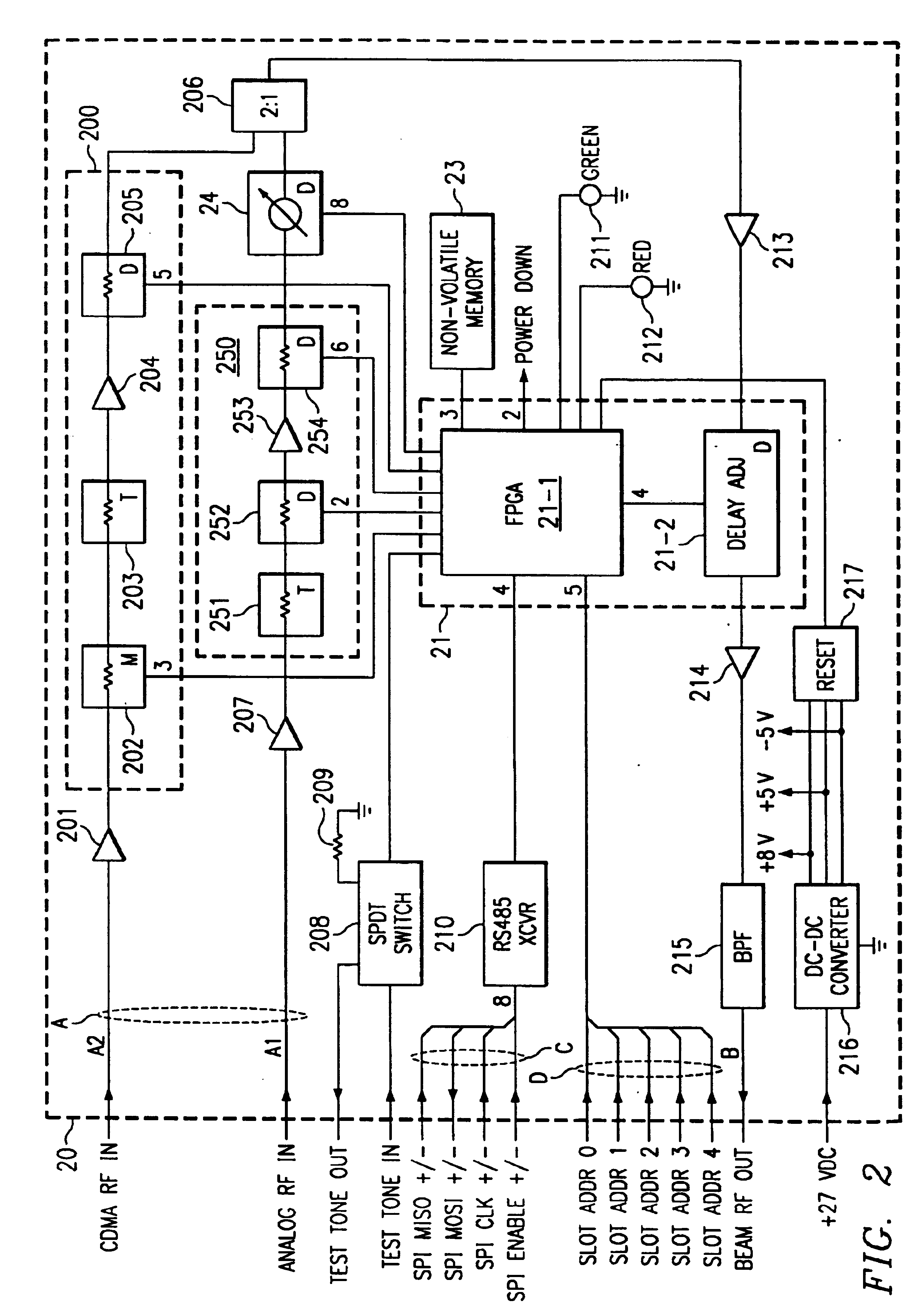
[0011]These and other objects, features and technical advantages are achieved by a system and method which provides a delay equalized transmission system that allows consistent pattern formation for a relatively wide range of frequencies. According to a preferred embodiment of the present invention, delay characteristics of various relevant transmission paths are measured and delay corrected to minimize the effects of a non-linear phase response and to equalize the linear phase delay among the transmission paths.
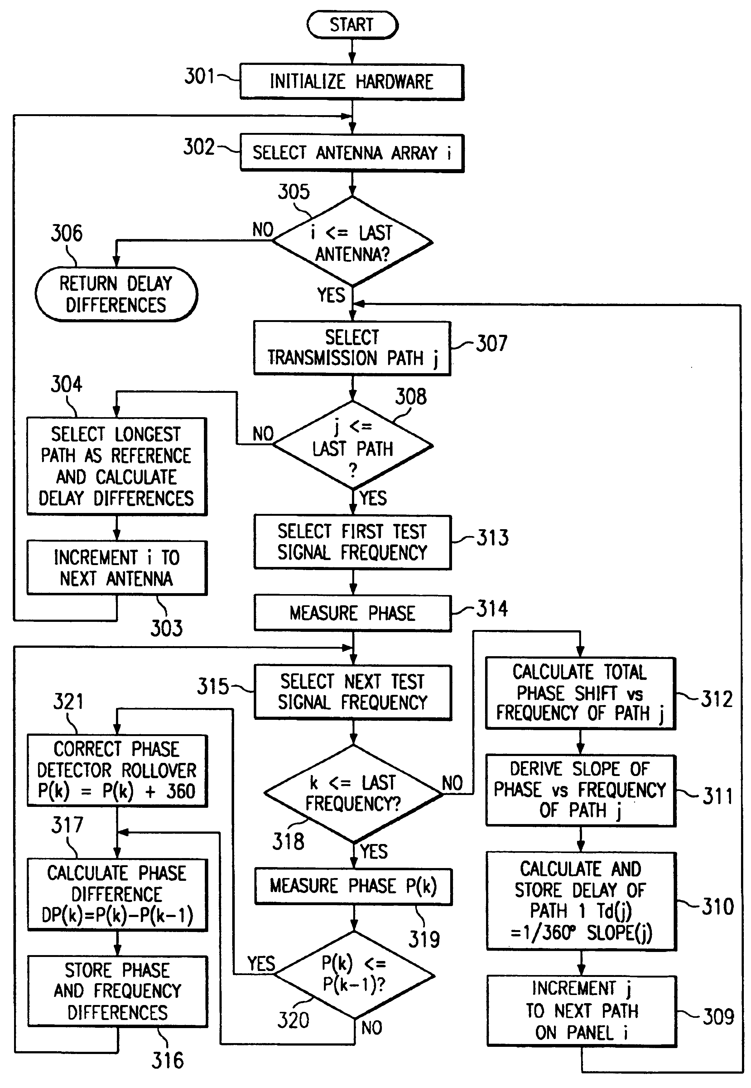
[0014]According to a preferred embodiment, a step frequency or swept frequency measurement is utilized in determining signal path delay. For example, the present invention may start at one end of the frequency band, measure the phase delay experienced, increment / decrement a predetermined amount of frequency, and again measure the phase delay experienced. Preferably the entire frequency band is stepped through, although some portion thereof might be utilized, such as a statistical sample. The frequency steps of the preferred embodiment are determined through reference to such factors as the length, physical and / or electrical, of the signal paths, the frequencies to be utilized therewith, and / or the like. Preferably, the steps are kept small enough that a phase rollover, i.e., a complete cycle, is not experienced in the phase detector. Such an embodiment is preferred because it simplifies the accumulation of the total amount of phase shift as the frequency band is stepped through.
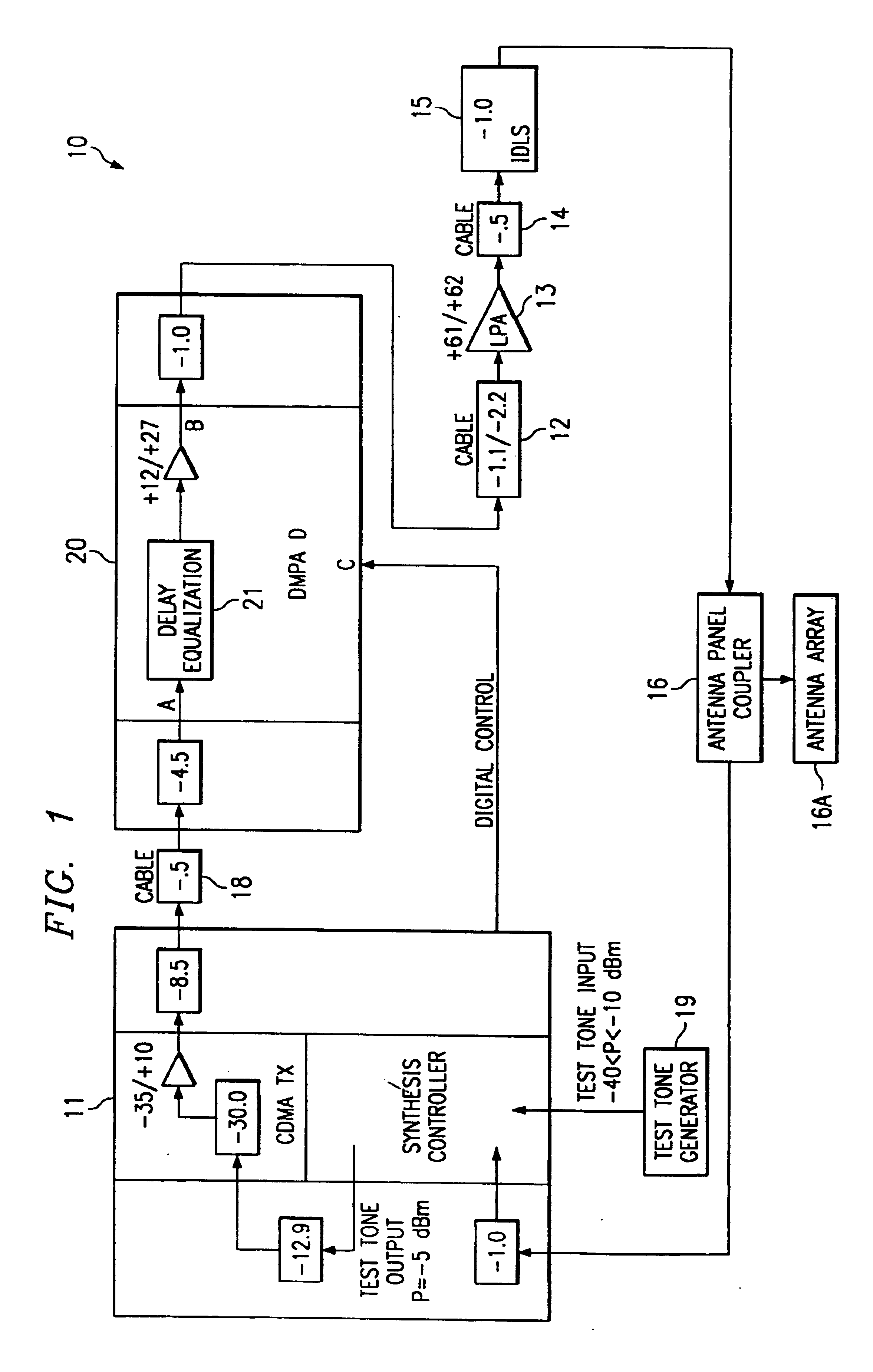
[0017]It should be appreciated that the electrical delay equalization of the present invention allows phase calibration of signal paths, such as the antenna beam signal paths coupling a phased array antenna panel to transceiver equipment, to hold over a broad range of operating frequencies. This permits formation of sector patterns that remain constant over the entire operating band. Such a technique is useful when using a multiple beam antenna system, such as those used in cellular telephony applications, where a number of signal paths, such as those of the various antenna beams, are utilized in communicating relatively low power signals in controlled areas, such as to promote frequency reuse and to improved signal quality and / or capacity. Moreover, the technique of the present invention is particularly useful with a dual mode system, such as the Spotlight® 2000 smart antenna system available from Metawave Communications Corporation, the assignee of the present application, where the frequency bands of multiple communication systems or networks, such as those of analog AMPS and digital PCS services, are communicated through common antenna structures.

Problems solved by technology

However, there is often an appreciable length of transmission line and a number of components, such as amplifiers and filters, disposed in the transmission lines between transceiver equipment and the antenna array.
There are often differences in the physical and / or electrical delays of the multiple paths, e.g., individual antenna beam signal paths, coupling an antenna array to associated transceiver equipment.
Accordingly, the phase of signals as provided to a beam forming matrix may experience differing amounts of delay and, thus, result in undesired phase differentials there between.
Moreover, there may be various electrical and / or physical path differences within a beam forming matrix.
Accordingly, the phase of signals as provided to the antenna elements of an antenna array may experience differing amounts of delay and, thus, result in undesired phase differentials there between.
Phase differences on the order of a few nanoseconds when providing beam forming for signals in the 800 MHz frequency range and up can result in significant degradation of the desired radiation pattern.
However, signal amplitude differentials are generally not experienced in sufficient magnitudes to significantly affect beam forming attributes.
Controlling (or knowing) the signals' relative phases after propagating through the different transmission paths is difficult because the different paths affect the phase of each signal differently.
The differing delays result from the paths having different electrical lengths and non-linearities associated with high order filters with steep roll-off characteristics.
However, such calibration is generally only effective for a particular operating frequency.
For example, RF signals as provided to a beam forming matrix, or as provided to the individual antenna elements of an antenna array, can be phase balanced at one frequency, but generally will not remain phase balanced within acceptable limits over a wide band of different frequencies.
Unfortunately, it is not practicable to re-calibrate a system for separate operating frequencies.
This problem is compounded when the frequency range is further widened.

Method used


Image

  • System and method for delay equalization of multiple transmission paths
  • System and method for delay equalization of multiple transmission paths
  • System and method for delay equalization of multiple transmission paths

Examples


Embodiment Construction

[0025]A. Overview

[0026]With a preferred embodiment of the present invention, a system and method are provided for averaging the effects of non-linear phase response and equalizing the electrical delays among the transmission paths that feed a phased-array antenna. Transmission path delay equalization according to the present invention facilitates broadband phase calibration of multiple element arrays.

[0027]With a constant electrical delay, there is a linear relationship between phase change versus frequency change. Thus, delay can be derived by taking the derivative of phase as a function of frequency. Accordingly, delay can be estimated by averaging differences in phase versus differences in frequency over an acceptable frequency range and extracting a linear component from the phase versus frequency function over this range.

[0028]In one embodiment, phase calibration of a number of transmission paths is generally performed according to the following steps. Initially, information is...


PUM


Abstract

The present invention provides systems and methods for addressing the effects of non-linear phase response, such as by equalizing electrical delays among transmission paths. A preferred embodiment provides phase detection circuitry and phase adjustment circuitry in the signal paths of a multiple beam or phased array antenna to provide delay equalization of the signal paths. Communication systems implementing the systems and methods of the present invention are provided broadband phase calibration and, therefore, are enabled to provide controlled and predictable beam forming over a broad range of frequencies.

Description

RELATED APPLICATIONS[0001]The present invention is related to co-pending and commonly assigned U.S. patent application Ser. No. 09 / 092,429 entitled “System and Method for Fully Self-Contained Calibration of an Antenna Array,” filed Jun. 5, 1998, the disclosure of which is hereby incorporated herein by reference.TECHNICAL FIELD[0002]The present invention generally relates to wireless communication systems. In particular, the present invention relates to a delay adjustment technique for signal paths in a wireless communication system.BACKGROUND[0003]Wireless communications often rely upon the controlled radiation / reception of radio frequency (RF) signals. For example a wireless communication system may utilize an antenna array adapted to radiate and / or receive signals within predefined areas, such as through the use of directional antenna beams. Such antenna beams may be formed using an array of multiple antenna elements arranged in a particular pattern, such as spaced a certain wave ...

Claims


Application Information

Patent Timeline
IPC IPC(8): G01S7/40H04B17/00H04B7/08
CPCH04B7/084
Inventor BLOUNT, RICHARD J.PETERSON, JAY D.
Owner F POSZAT HU
Learn More