
Management of limited resources in a graphics system

Inactive Publication Date: 2005-05-17
ACTIVISION PUBLISHING
View PDF10 Cites 38 Cited by
  • Summary
  • Abstract
  • Description
  • Claims
  • Application Information

AI Technical Summary

Benefits of technology

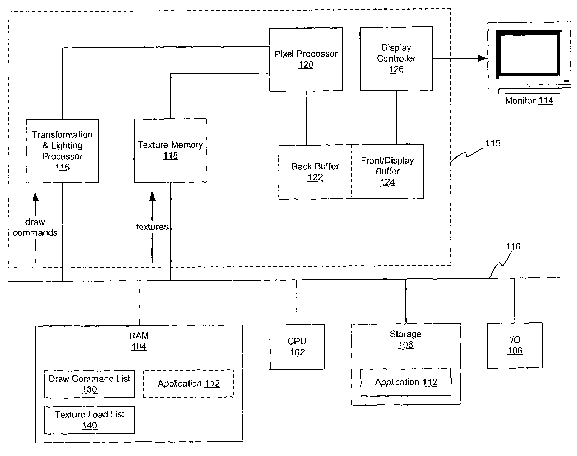
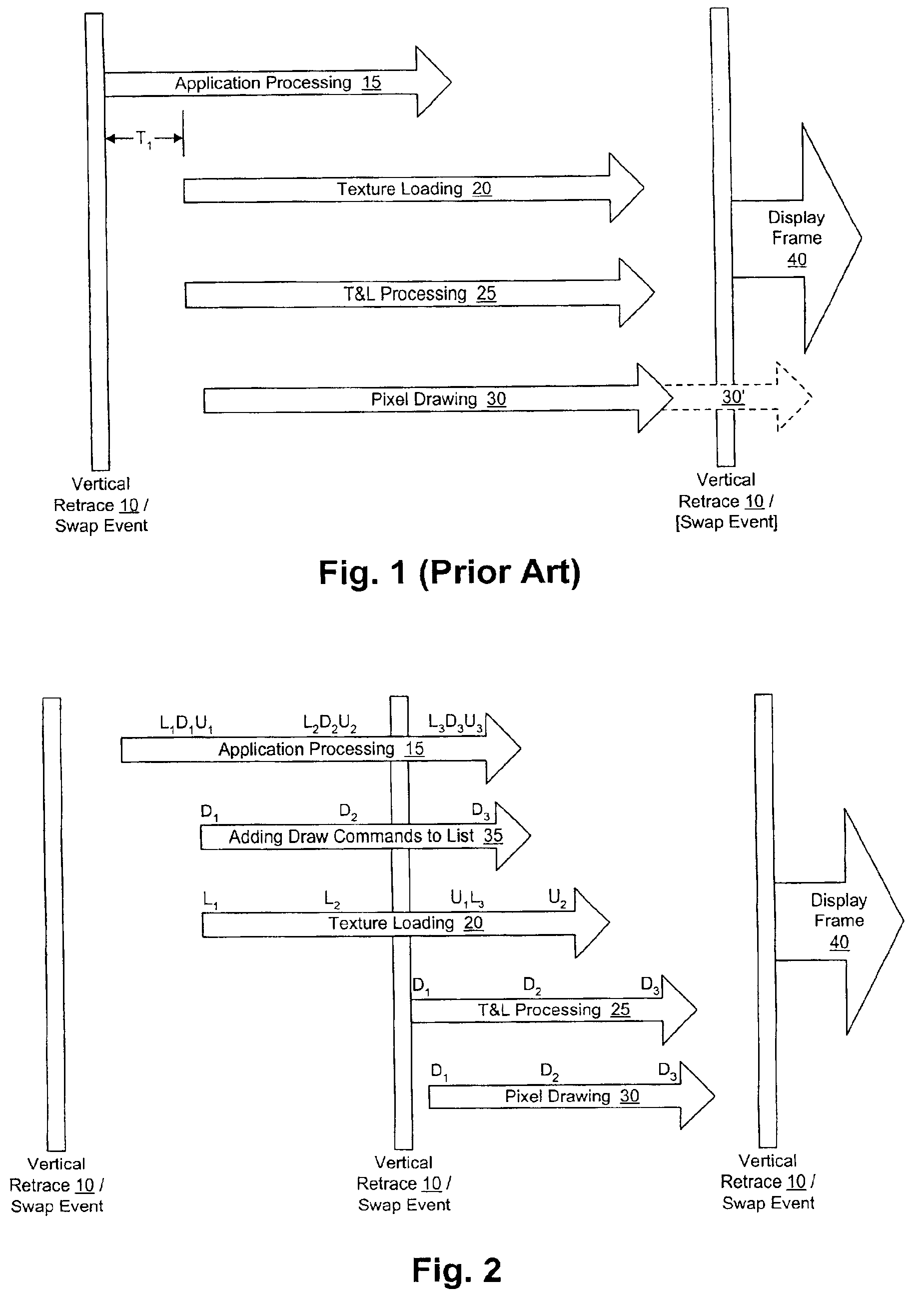
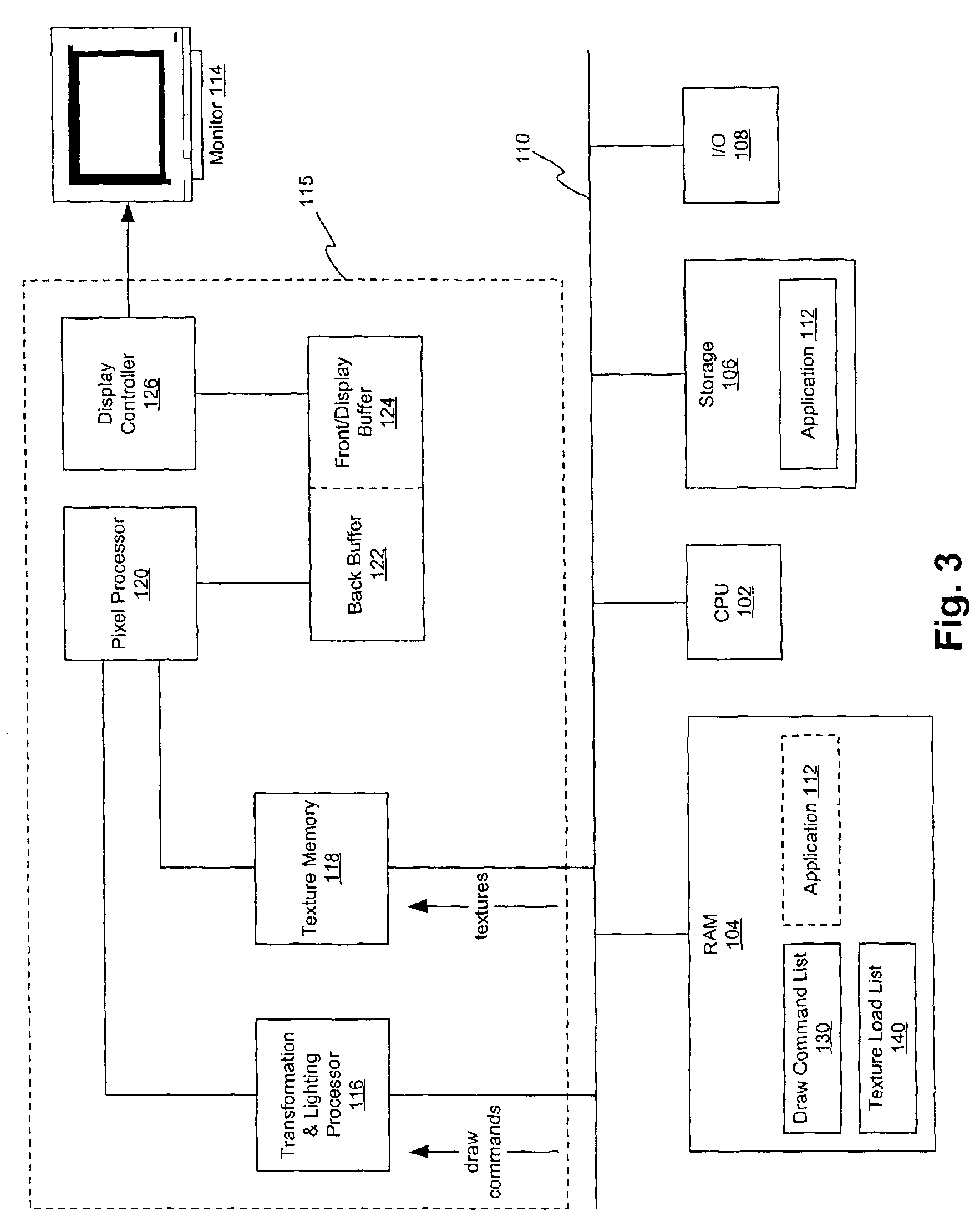
[0013]To overcome some of the problems of existing graphics systems, an embodiment of the present invention allows a graphics application to generate graphics commands for the next display frame before the swap event. In accordance with a preferred embodiment of the invention, a draw command list and associated logic are included in a graphics system. Rather than pausing the application's processing until a swap event, the task of preventing drawing before the frame buffer is available (e.g., until a swap event has occurred in a double-buffered system) is shifted to the draw command list and its associated logic. In this way, the application is allowed to “run ahead” by filling the draw command list with draw commands, or references thereto. Advantageously, a combination of buffering and synchronization techniques reduces the processing time wasted while waiting for a swap event and texture loading, thus increasing the performance of the graphics system.
[0015]In an embodiment, entries in the draw command list include one or more predicate functions that are satisfied when a swap event occurs. With this predicate function, the draw commands in this entry and all subsequent entries are held in the draw command list until the swap event. Accordingly, this predicate function allows the application to continue to run and generate draw commands for a next frame while ensuring that the draw commands for the next frame will not be sent too soon to the T&L processor (e.g., before the swap event). In another embodiment, entries in the draw command list include one or more predicate functions that are satisfied when one or more textures are loaded in the texture memory. These predicate functions allow the application to continue to issue draw commands without having to manage texture loading synchronization or wait for texture memory to become available.
[0016]In one embodiment, textures are loaded into the texture memory by the application as the graphics data are processed. Textures are placed in the texture memory according to a linear, first-fit algorithm, and they are unloaded after the pixel processor uses them in conjunction with a draw command. In another embodiment, the application stores instructions for leading textures in a texture load list, preferably implemented as a FIFO queue, allowing the application to continue to run and generate graphical data. Advantageously, the application does not have to wait for texture memory to become available before issuing a texture load instruction.
[0017]In another aspect of an embodiment, a development environment is provided for producing an application in accordance with any of the embodiments described herein. The development environment combines program code received from a developer with the synchronization and list logic required to manage the transfer of draw commands and loading of textures. By including this functionality on a low level in the application development process that is “invisible” to developers, developers of computer games and other graphics applications obtain the benefits of the invention without having to specifically incorporate the functionalities in each piece of software they write.

Problems solved by technology

However, hardware resources are limited, e.g., by memory, bus availability, and processor speeds, which in turn limit the performance of the software.
One of the limited resources in a graphics system is texture memory.
In typical systems, 60 to 100 or more display frames are drawn every second, resulting in a need for a large texture memory and high memory bandwidth.
Another limitation is the speed of the processors.
Typical double-buffered graphics systems do not allow drawing to occur while the target frame buffer memory (i.e., the front buffer in a double-buffered system) is being displayed.
Because of this limitation, applications must wait until a vertical retrace before processing graphics commands for the next frame.
This waiting wastes a significant amount of CPU time and further underutilizes the T&L and pixel processors during this time.
But it also wastes processing time because the application typically has some CPU-bound compute time (e.g., scene graph traversal, physics calculations, animation, etc.) before the application sends draw commands to the T&L processor and textures to the texture memory.
In this case, the front buffer does not change, and the monitor continues to display 40 the same frame, thereby causing the frame rate performance to drop and thus diminishing the quality of the display.
In this case, the partially drawn buffer is displayed on the monitor, which results in display artifacts such as “tearing.” On the monitor, tearing causes the next displayed frame to be composed of a portion of the last frame and a portion of the next frame, which is also undesirable.
A significant factor that leads to inefficiency in existing systems is the loss of processing time due to the system's waiting for a vertical retrace to begin before processing the next frame.
These constraints are complicated by the structure of typical graphics system hardware, which allows for asynchronous transformation and drawing processing and asynchronous texture loading.
Moreover, implementing synchronization operations with the application is undesirably complex.

Method used


Image

  • Management of limited resources in a graphics system
  • Management of limited resources in a graphics system
  • Management of limited resources in a graphics system

Examples


Embodiment Construction

[0027]FIG. 2 is an event diagram that illustrates the processing that occurs for a particular frame according to a preferred embodiment of a graphics system. An embodiment of the hardware architecture of a double-buffered graphics system for performing the operations shown in FIG. 2 is described in greater detail in connection with FIG. 3.

[0028]Some of the advantages of the invention can be appreciated by comparing the operation of an embodiment of the invention shown in FIG. 2 with that of a typical system shown in FIG. 1. In FIG. 2, the application is allowed to process 15 graphics data for a next frame before the swap event (which in this example is synched with the monitor's vertical retrace 10). Preferably, the application begins to process 15 graphics data for the frame shortly after the application processing for the previous frame ends (not shown), which minimizes or eliminates the amount of time the CPU is idle. When the application processing 15 begins for the frame, the a...


PUM


Abstract

A graphics application generates graphics data, including draw commands and instructions to load textures. The application loads draw commands into a list and associated logic for later transfer to graphics hardware. Draw commands may be associated with one or more predicate functions that prevent the commands from being transferred before the graphics hardware is ready to receive them. The application further loads textures into a texture memory or stores instructions for loading textures in a texture load list. A development environment allows such applications to be developed without requiring developers to specifically code these functionalities.

Description

CROSS REFERENCE TO RELATED APPLICATIONS[0001]This application claims the benefit under 35 U.S.C. § 119(e) of U.S. Provisional Application No. 60 / 267,904, filed Feb. 9, 2001, which is hereby incorporated in its entirety by reference.BACKGROUND OF THE INVENTION[0002]1. Field of the Invention[0003]The present invention relates generally to the management of limited resources in a computer graphics system and, in particular, to improving the performance of graphics systems through pre-loading and synchronization of draw commands and textures.[0004]2. Description of Background Art[0005]Computer games and other graphics-intensive software applications demand increasing performance from the graphics hardware upon which they run. However, hardware resources are limited, e.g., by memory, bus availability, and processor speeds, which in turn limit the performance of the software. Therefore, optimizing the use of these limited resources available to application developers is critical to the ov...

Claims


Application Information

Patent Timeline
IPC IPC(8): G06T15/00
CPCG06T15/005
Inventor NASH, REUEL W.
Owner ACTIVISION PUBLISHING
Learn More