Internal combustion engine

Inactive Publication Date: 2005-05-17
HONDA MOTOR CO LTD
View PDF12 Cites 5 Cited by
  • Summary
  • Abstract
  • Description
  • Claims
  • Application Information

AI Technical Summary

Benefits of technology

[0007]In view of such circumstances, it is an object of the present invention to provide an internal combustion engine which can generate a strong swirl by increasing the amount of intake air for generating the swirl in a simple structure.
[0009]Accordingly, the first plane including the first inlet slot defines a bevel inclining upwardly as it approaches from the position near the outer periphery of the combustion chamber toward the second reference plane in the direction of the rotational centerline. In addition, the line of intersection is not parallel with the third reference plane, which is a plane extending orthogonally to the cylinder axis. Therefore, the diameter of the first inlet slot in the direction of the rotational centerline can be increased so that the opening area is increased in comparison with the related art in which the line of intersection between the plane including the inlet slot through which intake air for generating the swirl flows in and the plane extending in parallel with the first reference plane extends in parallel with the third reference plane. In addition, since the port section of the first port is the passage extending in the direction orthogonal to the first inlet slot in a plan view, the width of the passage in a plan view, which is a factor for determining the cross-sectional area at the port section extending from the first inlet slot to the upstream (the area of the passage along a plane orthogonal to the streamline of intake air) can be maximized.
[0010]As a consequence, according to the present invention, the following effects are achieved. In the first inlet slot, the opening area of the first inlet slot can be increased and the width of the port section in a plan view can be maximized to increase the cross-sectional area of the passage in a simple structure in which the line of intersection between the first plane and the first orthogonal plane inclines as it approaches from the position near the outer periphery of the combustion chamber toward the second reference plane, and the first port includes the port section having a passage shape extending from the first inlet slot to the upstream substantially along the perpendicular line in a plan view. Therefore, when the intake air control means generates a swirl in the combustion chamber by intake air flowing from the first port, the amount of intake air for generating the swirl flowing into the combustion chamber from the first inlet slot can be increased, and thus a strong swirl can be generated. Consequently, the combustibility of the lean combustion is further improved, which enables combustion with a leaner air-fuel mixture, and thus fuel consumption is decreased. In addition, since squeezing of intake air flowing into the combustion chamber when generating the swirl may be avoided irrespective of generating a strong swirl, the pumping loss may be reduced, which also contributes to a reduction in fuel consumption.
[0012]Accordingly, the first inlet slot is opened and closed by the first intake valve which is formed of the poppet valve and is included in the beveled plane inclining upwardly as it approaches from the position near the outer periphery of the combustion chamber toward the reference plane. Thus, the diameter of the first inlet slot in the direction of the rotational centerline may be increased to increase the opening area in comparison with the related art in which the inlet slot through which intake air for generating a swirl that is flowing in is not changed in level in the direction of the rotational centerline. In addition, since the port section of the first port is a passage extending in the direction substantially orthogonal to the first inlet slot in a plan view, the width of the passage in a plan view, which is a factor for determining the cross-sectional area at the port section extending from the first inlet slot to the upstream (the area of the passage along a plane orthogonal to the streamline of intake air) can be maximized.
[0013]Consequently, according to the present invention, since the first intake valve is disposed so as to gradually approach the reference plane as the axis of the valve stem approaches the side of the distal end of the valve stem toward the side of the bevel portion of the intake valve in a plan view, and the first port includes the port section having a passage shape extending substantially along the axis of the valve stem from the first inlet slot to the upstream by a predetermined passage length in plan view, in the internal combustion engine including the valve mechanism having a valve halting mechanism for opening and closing the first intake valve formed of the poppet valve and halting the second intake valve in the specific operating range, the amount of intake air for generating the swirl flowing into the combustion chamber from the first inlet slot can be increased when the valve halting mechanism halts the second intake valve.

Problems solved by technology

Therefore, there is not enough space for increasing the diameter of the first inlet slot on the combustion chamber having a predetermined diameter.
Thus, it is difficult to increase the amount of intake air for generating the swirl by increasing the area of the first inlet slot so as to generate a strong swirl.

Method used


Image

  • Internal combustion engine
  • Internal combustion engine
  • Internal combustion engine

Examples


Embodiment Construction

[0021]Referring now to FIG. 1 to FIG. 4, an embodiment of the present invention will be described.

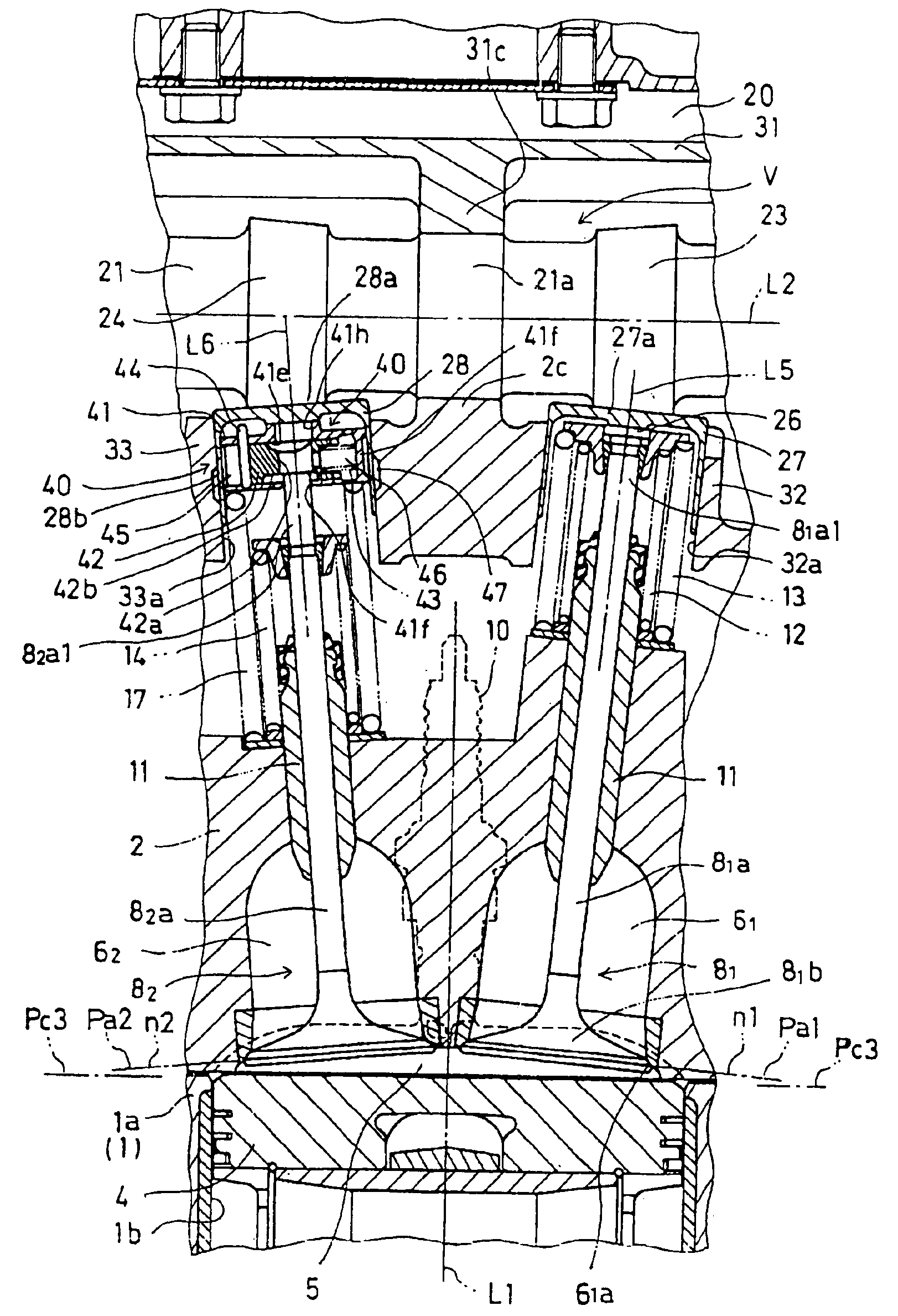
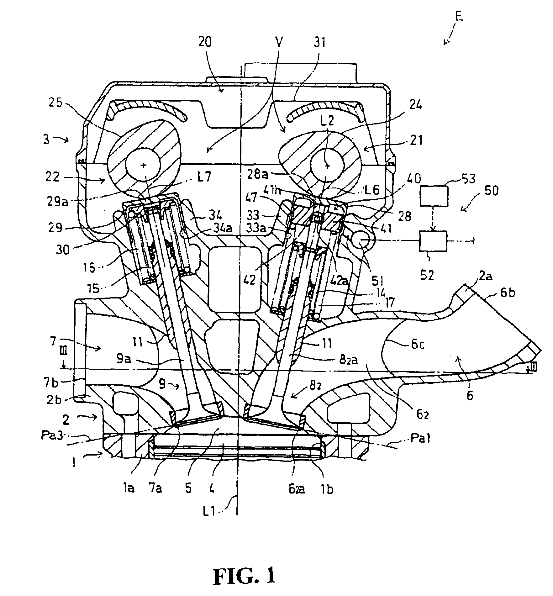
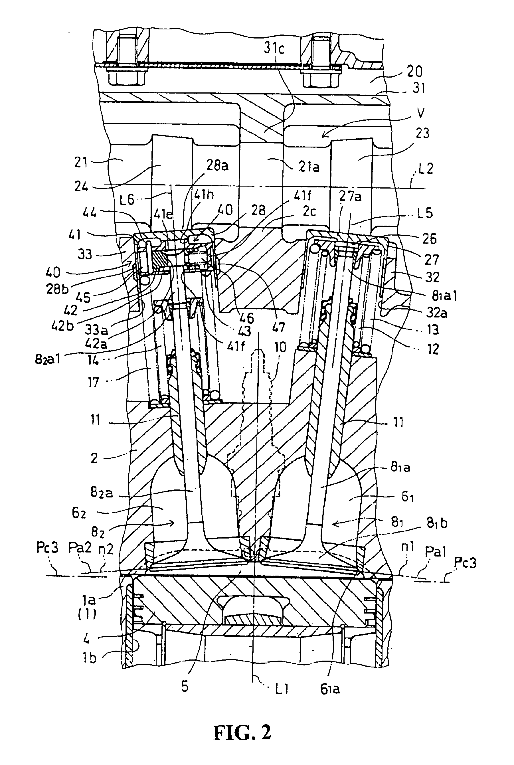
[0022]In FIGS. 1 to FIG. 3, an internal combustion engine E to which the present invention is applied is a DOHC in-line 4-cylinder, 4-stroke internal combustion engine to be mounted to a motorcycle, which burns with a lean air-fuel mixture. In FIG. 1 and FIG. 2, the internal combustion engine E includes a cylinder block 1 to the lower end of which a crankcase is connected, a cylinder head 2 to be connected to the upper end of the cylinder block 1, and a head cover 3 to be connected to the upper end of the cylinder head 2.

[0023]Pistons 4 fit into cylinder bores 1b for four cylinders 1a formed in the cylinder block 1 so as to be capable of a reciprocating motion. Each piston 4 is connected to a crankshaft rotatably supported by the crankcase via a connecting rod that rotates the crankshaft.

[0024]For each cylinder 1a, the cylinder head 2 is formed with a recess on the lower surface thereof...


PUM


Abstract

To provide an internal combustion engine that can generate a strong swirl by increasing the amount of intake air for generating the swirl in a simple structure. In the internal combustion engine provided with a cylinder head formed with an air intake port having first and second ports, when a second intake valve for opening and closing the second port is brought into a halted state by a valve halting mechanism, a swirl is generated by intake air flowing through the first port in a combustion chamber. At a first inlet slot, the line of intersection between a first plane, which is a plan including the first inlet slot and a first orthogonal plane inclines upwardly as it approaches from the position near the outer periphery of the combustion chamber towards a second reference plane, and the first port includes a port section having a passage shape which extends substantially along a perpendicular line orthogonal to a first plane from the first inlet slot towards the upstream by a predetermined length of the passage in a plan view.

Description

CROSS-REFERENCE TO RELATED APPLICATIONS[0001]The present application claims priority under 35 USC 119 to Japanese Patent Application No. 2003-045700 filed on Feb. 24, 2003 the entire contents thereof is hereby incorporated by reference.BACKGROUND OF THE INVENTION[0002]1. Field of the Invention[0003]The present invention relates to an internal combustion engine including a cylinder head formed with an air intake port having first and second ports including first and second inlet slots opening into a combustion chamber, respectively, wherein a swirl is generated by intake air flowing through the first port.[0004]2. Description of Background Art[0005]An example of an internal combustion engine is disclosed in JP-A-11-50852 in which a swirl is generated in a combustion chamber during an intake stroke in order to improve a combustibility of the lean air-fuel mixture. In this internal combustion engine, a cylinder head is formed with first and second intake ports which communicate respect...

Claims


Application Information

Patent Timeline
IPC IPC(8): F02B31/00F02B31/08F02D13/06F02F1/42F01L1/14F01L13/00F02B31/02
CPCF01L1/022F01L1/143F01L13/0005F02B31/08F02B31/087F02D13/06F01L1/08F01L1/462Y02T10/18Y02T10/146F01L2003/256Y02T10/12
Inventor TSUKUI, TAKAAKI
Owner HONDA MOTOR CO LTD
Why Eureka
Try Eureka