High-speed S module multi-return-stroke heat exchanger

A multi-return, heat exchanger technology, applied in the direction of heat exchanger types, heat exchanger shells, indirect heat exchangers, etc., to achieve the effects of prolonging service life, saving construction investment, and increasing stroke length

Pending Publication Date: 2018-03-16
西安华广电站锅炉有限公司
View PDF0 Cites 0 Cited by
  • Summary
  • Abstract
  • Description
  • Claims
  • Application Information

AI Technical Summary

Problems solved by technology

[0004] The technical problem to be solved by the present invention is to overcome the shortcomings of existing heat exchangers and provide a high-speed S-module multi-return heat exchange with high pressure bearing capacity, compact structure, large volume, convenient maintenance, long service life and high heat exchange efficiency device

Method used


Image

  • High-speed S module multi-return-stroke heat exchanger
  • High-speed S module multi-return-stroke heat exchanger
  • High-speed S module multi-return-stroke heat exchanger

Examples


Embodiment Construction

[0024] The present invention will be described in further detail below with reference to the drawings and examples, but the present invention is not limited to the following embodiments.

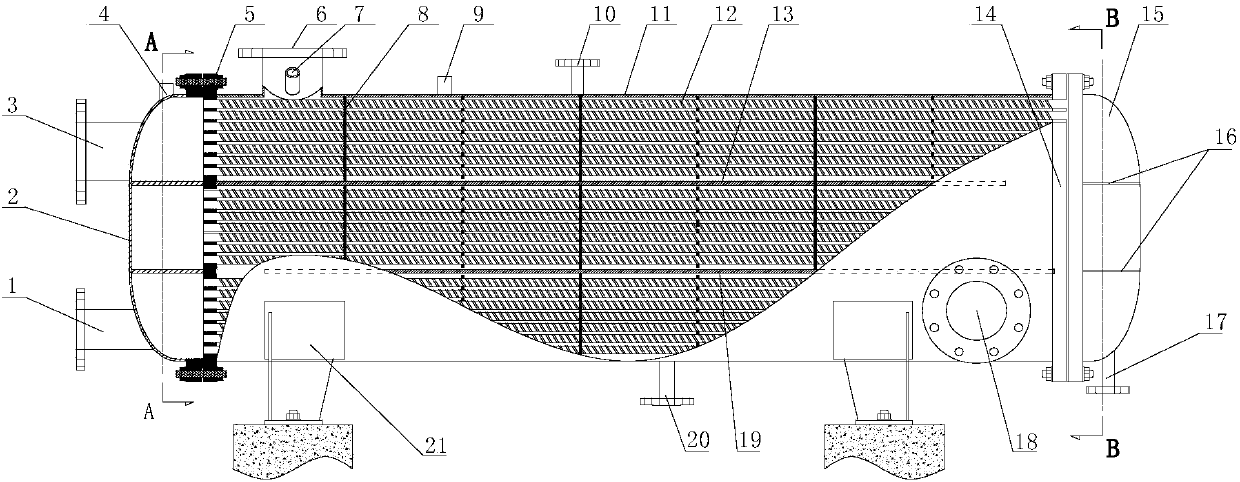
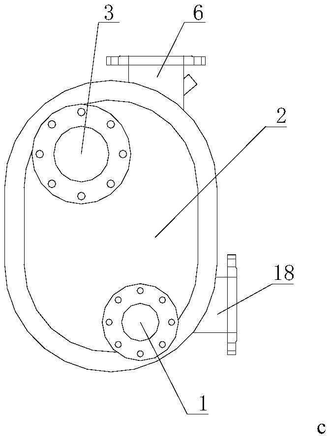
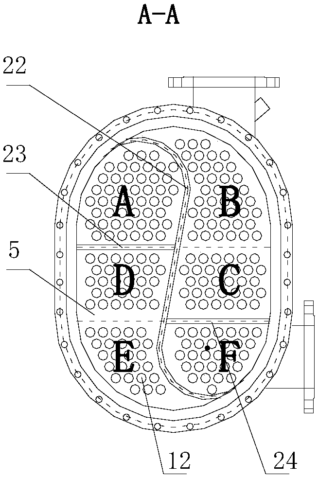
[0025] exist Figure 1~4 Among them, the high-speed S-module multi-return heat exchanger of the present invention consists of a heat source outlet flange 1, a first head 2, a heat source inlet flange 3, a tube side pressure gauge interface 4, a first tube plate 5, and a cold source outlet flange 6. Thermometer interface 7, baffle plate 8, shell side pressure gauge interface 9, safety valve interface 10, shell 11, heat exchange tube 12, second deflector plate 13, second tube plate 14, second head 15 , the fourth head partition 16, the pipe-side blowdown valve interface 17, the cold source inlet flange 18, the first deflector 19, the shell-side blowdown valve interface 20, the mounting support 21, the first head partition 22, The second head partition 23 and the third head partition 24 are co...


PUM


Abstract

The invention discloses a high-speed S module multi-return-stroke heat exchanger. One end of a shell is connected with a first seal head through bolts, and the other end of the shell is connected witha second seal head through bolts; the first seal head is provided with a heat source inlet flange, a heat source outlet flange and a tube pass pressure meter connector; the second seal head is provided with a tube pass blow-down valve connector; the shell is provided with a temperature meter connector, a safety valve connector, a shell pass blow-down valve connector and a shell pass pressure meter connector; a first tube plate is installed between the shell and the first seal head, and a second tube plate is installed between the shell and the second seal head; one ends of heat exchange tubesare fixed to the first tube plate, and the other ends of the heat exchange tubes are fixed to the second tube plate; the heat source inlet flange, the heat source outlet flange, the first seal head,the heat exchange tubes and the second seal head form a tube pass, and a heat source flows in the tube pass; and a cold source outlet flange is welded to the position, close to the upper end of the first seal head, of the shell, a cold source inlet flange is welded to the position, close to the lower end of the second seal head, of the shell, and the cold source inlet flange, the shell and the cold source outlet flange form a shell pass.

Description

technical field [0001] The invention belongs to the technical field of heat exchange equipment, and in particular relates to a heat exchanger. Background technique [0002] Existing bellows heat exchangers and tube-and-tube heat exchangers are all forced turbulent flow heat exchangers, which form the tube side where the cold source is located by fixing multiple straight-through heat exchange tubes between two tube sheets. The shell where the heat source is located, the heat source is inside the shell, the heat dissipation loss is large, the heat exchange efficiency is low, and the occupied area is large. When used in condensers or heating network heaters, the steam will naturally condense through heat release in the shell and convert into condensed water. The condensed water has a high temperature and low pressure. It must be equipped with a steam trap and a condensed water chamber to work normally. And it is not easy to recycle, it needs a special condensate pump and conde...

Claims


Application Information

Patent Timeline
Patent Type & Authority Applications(China)
IPC IPC(8): F28D7/16F28F9/12F28F21/08F28F9/24
CPCF28D7/16F28F9/12F28F9/24F28F21/082
Inventor 冉照杰冉东成冉东汶汪宗海
Owner 西安华广电站锅炉有限公司
Why Eureka
Try Eureka