Method and device for pacing an image reader at a constant scanning speed

a technology of scanning speed and image reader, which is applied in the direction of electrographic process apparatus, printers, instruments, etc., can solve the problems of speed fluctuations, inability to obtain image data precisely, and irregular traveling speed of light source lamps, so as to eliminate speed fluctuations, precise image data, and eliminate speed fluctuations

Inactive Publication Date: 2005-05-10
FUJI PHOTO OPTICAL CO LTD
View PDF3 Cites 3 Cited by
  • Summary
  • Abstract
  • Description
  • Claims
  • Application Information

AI Technical Summary

Benefits of technology

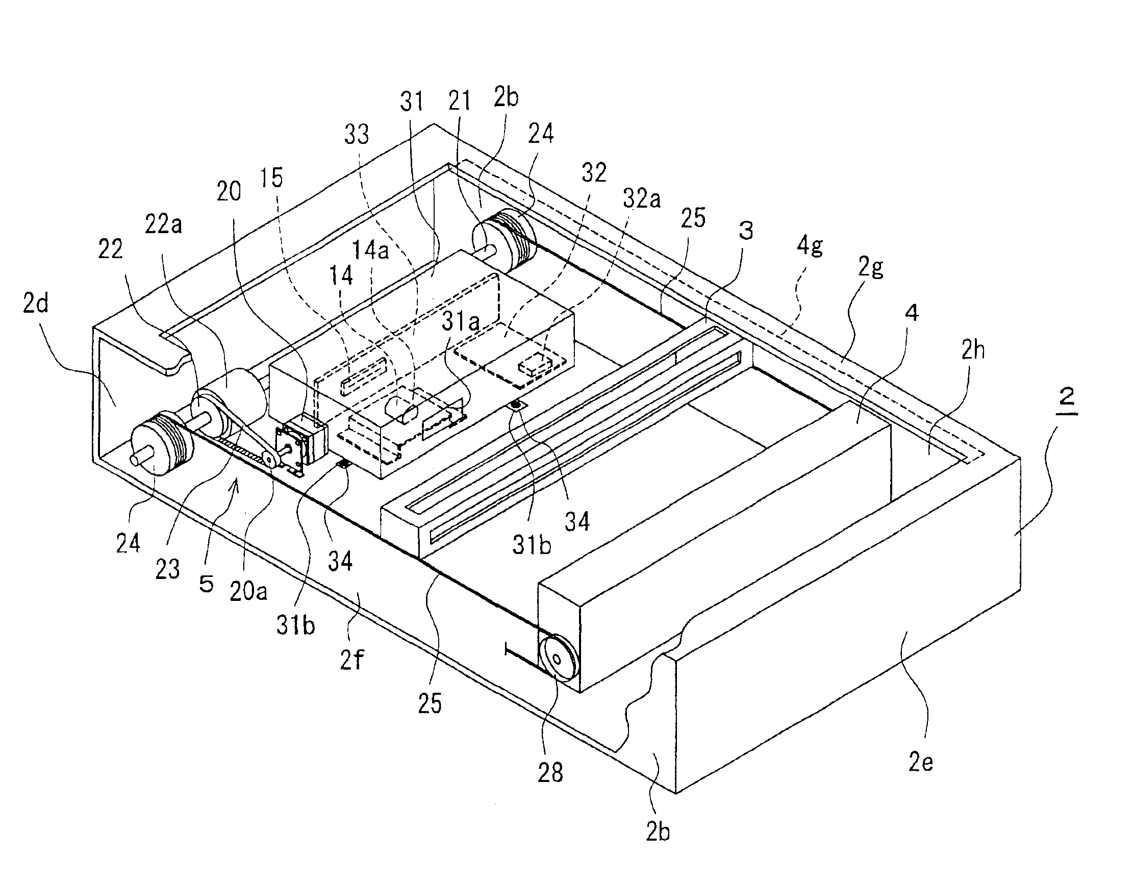
[0008]To eliminate such speed fluctuations, the present inventors tried various efforts, noticed the characteristics of the drive motor, and achieved a certain result in elimination of speed fluctuations by adjusting the supply current. The object of the present invention is to offer a method and a device for pacing an image reader at a constant scanning speed to obtain precise image data by minimizing speed fluctuations at the drive motor in the image reader to assure the light source lamp travels at a constant speed.
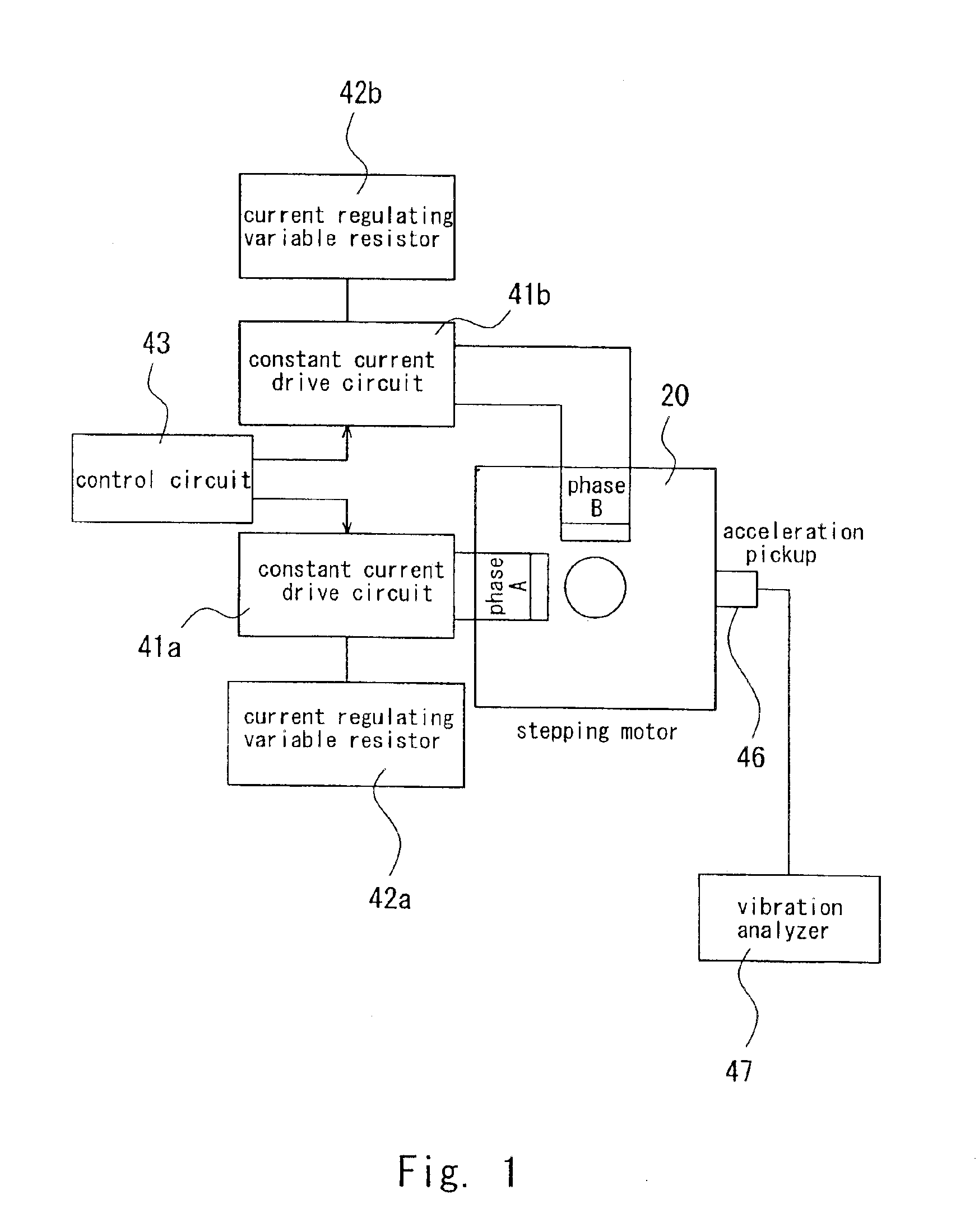
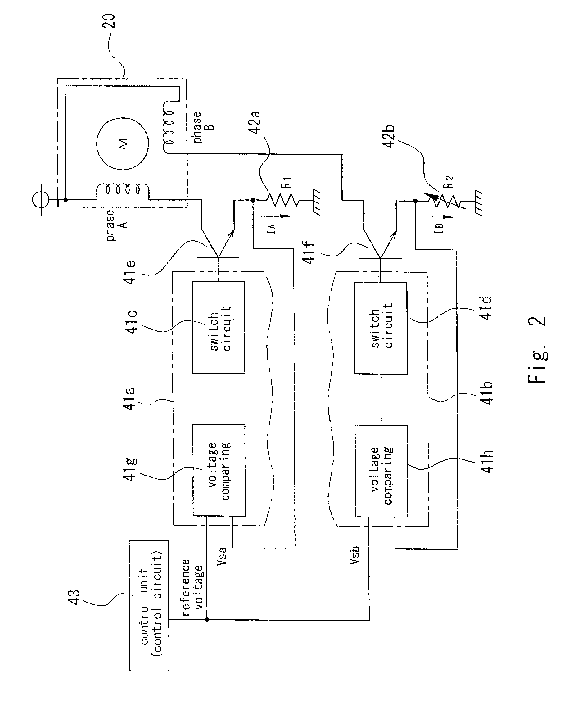
[0013]A drive motor is installed in an image reader, supplied with current at an equal value at each phases, while changing the current value at one of the phases to set a value to minimize speed fluctuations at the drive motor. Speed fluctuations at the drive motor depend on the difference among individual drive motors. Therefore, a drive motor can be adjusted, as installed in an image reader, to make it easy for the drive motor to pace at a constant speed, by making the current value adjustable at each phase in accordance with the respective drive motors.
[0022]As mentioned above, a drive motor can work at a constant speed, supplied with a two-phase current with difference in current value or changing the current value ratio, thus allowing a light source lamp to travel at a constant speed during a scan, to obtain image data faithful to an image on an original.
[0024]The current value can be changed at least at either phase by adjusting a resistance value at the above variable resistor, when supplied to a drive motor, thus allowing the two-phase current to have a different current value ratio which can be adjusted to be as large as needed. As a result, the drive motor can be kept rotating at a constant speed, as installed in an image reader.
[0033]Then, the device for pacing an image reader at a constant scanning speed according to the present invention is characterized in that a tentative scan is tried, with a test chart, placed somewhere on the platen glass or on the underside of the top plate of the housing to avoid any harm in obtaining image data of an original, to obtain image data for measurement from the test chart, to detect speed fluctuations at the light source lamp from the image data for measurement, and to adjust, based on the detected result, to make difference in current value at each phase of the two-phase current, before a definitive scan to obtain image data.
[0037]Then, the device for pacing an image reader at a constant scanning speed according to the present invention is characterized in that it comprises vibration proofing means to prevent vibration at the drive motor from being transmitted to the light receptor.

Problems solved by technology

On the other hand, the drive motor has a little irregularity in rotation by its own nature, causing speed fluctuations to result also in irregularity in traveling speed of the light source lamp, sometimes failing to obtain image data precisely enough to satisfy the requirements for high image quality.
This type of speed fluctuations, caused by the characteristics of the drive motor itself, cannot always be eliminated by a known structure where an inertia spindle is conventionally used to smooth the rotation.

Method used


Image

  • Method and device for pacing an image reader at a constant scanning speed
  • Method and device for pacing an image reader at a constant scanning speed
  • Method and device for pacing an image reader at a constant scanning speed

Examples


first embodiment

[0090]In the cooling structure as shown in FIGS. 15 and 16, drive IC 32a is integrated at the center of drive circuit substrate 32. It has ventilation duct 52 at a part of lens cover 51 faced with drive IC 32a. Ventilation duct 52 is open at one end to face drive IC 32a and open on the upper face of lens cover 51 at the other end.

[0091]In the speed stabilizer equipped with a cooling structure according to the first embodiment, drive IC 32a is cooled, as spaced from the inside of lens cover 51 and kept in touch with the air outside lens cover 51. Then, it can minimize speed fluctuations due to change in temperature at drive motor 20 driven by drive IC 32a.

second embodiment

[0092]In the cooling structure as shown in FIGS. 17 and 18 drive IC 32a is integrated at the center of drive circuit 32. IC housing 57 is arranged with a pair of inner wall plates 57a and 57b to partition an inner corner of lens cover 56. Drive IC 32a is housed in this IC housing 57 and drive circuit substrate 32 should also preferably be placed in this IC housing 57. Then, a part of lens cover 56 is enclosed with this IC housing 57 and perforated with many through holes 58 through which IC housing 57 communicates between its own inside and outside.

[0093]In the speed stabilizer equipped with the cooling structure of this second embodiment, drive IC 32a is isolated by IC housing 57, while the inside of IC housing 57 communicates with the outside of lens cover 56 by means of through holes 58, to ventilate the air inside IC housing 57 and to cool drive IC 32a, thereby minimizing speed fluctuations due to change in temperature at drive motor 20 driven by drive IC 32.

[0094]In the third ...

fourth embodiment

[0095]In the fourth embodiment as shown in FIG. 21 relating to the above cooling structure, drive IC 32a is integrated at an end of drive circuit substrate 32. Lens cover 66 has a notch 66a, where faced with the drive circuit substrate 32, to allow insertion of the drive circuit substrate 32 from the lower end. An end of drive circuit substrate 32 projects from this notch 66a to outside of lens cover 66 and drive IC 32a is integrated at this projection. In other words, drive IC 32a is placed outside lens cover 66.

[0096]In the speed stabilizer equipped with a cooling structure of the fourth embodiment, drive IC 32a is cooled, as exposed to the air outside lens cover 66, thereby minimizing speed fluctuations due to change in temperature at drive motor 20 driven by drive IC 32a.

[0097]FIG. 22 shows the fifth embodiment of cooling structure, and FIG. 23 shows the sixth embodiment of the same. FIG. 24 shows a conventional structure used prior to these invention embodiments. In the conven...


PUM


Abstract

Speed fluctuations at a motor supplied with a two-phase current is reduced by changing the current value ratio at each phase in the drive current to feed a drive motor for an image reader to allow a light source lamp to move, free from speed fluctuations, to scan at a constant scanning speed. The drive motor is supplied with current different in value at each phase from constant current drive circuits, which, in one embodiment, are connected with current regulating variable resistors. An acceleration detector is fixed at the drive motor to detect acceleration fluctuations in rotation of the drive motor to detect speed fluctuations. In some embodiments, thermal control of the motor drive circuit is provided and vibration proofing to isolate the light receptor from the drive motor.

Description

BACKGROUND OF THE INVENTION[0001]1. Field of the Invention[0002]The present invention relates to a method and a device for pacing an image reader at a constant scanning speed, to stabilize the speed of a drive motor in an image reader, e.g. such as a copying machine, scanner or the like, thereby keeping a constant speed in reading an image.[0003]2. Description of the Related Art[0004]An image reader, such as a copying machine, scanner, etc., used to read and process image data on an original of a paper sheet etc. comprises a light source lamp such as a fluorescent lamp to irradiate light beams on an original and a light receptor with a photoelectric converter device such as CCD (Charge-Coupled Device) to receive the reflected light. The image reader for stationary original such as described in Japanese Laid-Open Patent Application No. 1998-257252 irradiates light beams onto an original on a platen glass, with a moving light source lamp. Then, a reflector or the like is arranged to g...

Claims


Application Information

Patent Timeline
Patent Type & Authority Patents(United States)
IPC IPC(8): G03B27/50G03G15/04G03G15/00G03G15/30H04N1/04
CPCG03G15/04G03G2215/0448
Inventor HAYASHI, EIICHIOGATA, KAZUTSUGUISHIYAMA, YUICHISHINOHARA, OSAMUMIKAJIRI, SATOSHI
Owner FUJI PHOTO OPTICAL CO LTD
Why Eureka
Try Eureka