
Sensor and method for detecting oil deterioration and oil level

a sensor and oil level technology, applied in the oil field, can solve the problems of trouble codes, affecting the capacitance of the sensor, unsatisfactory effect of the sensor output signal, etc., and achieve the effect of reducing size and reducing siz

Inactive Publication Date: 2012-12-25
SUN YIZHONG
View PDF21 Cites 18 Cited by
  • Summary
  • Abstract
  • Description
  • Claims
  • Application Information

AI Technical Summary

Benefits of technology

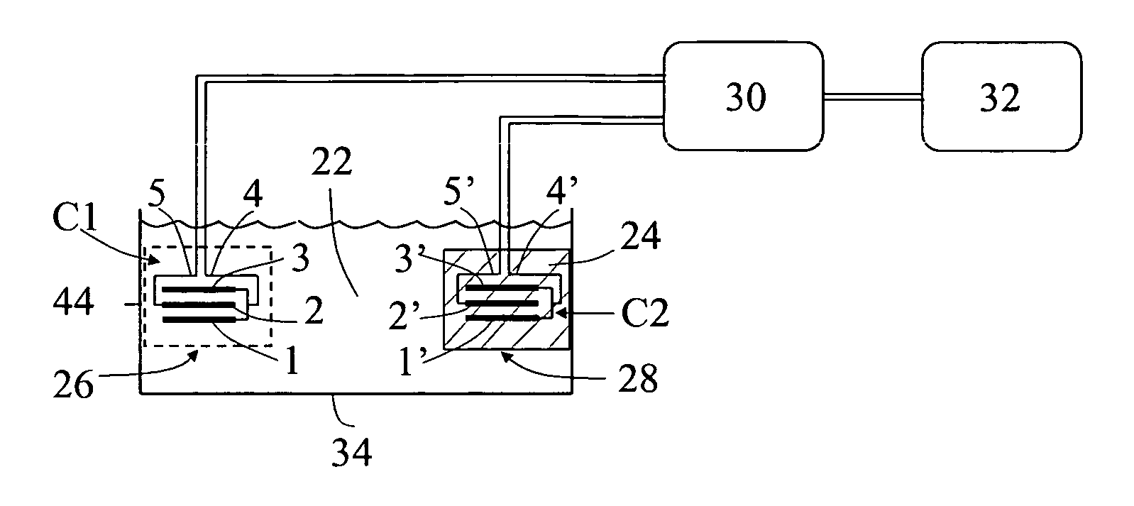
"The present invention is a sensor and method for detecting oil conditions, including oil deterioration, oil level, and oil usage. The sensor uses a measurement sensor with a capacitive sensing technology that detects changes in the oil's electrical properties. The sensor has two plated spatial electrodes that are positioned parallel to each other and are connected by a first lead wire, which serves as the first electrical pole. The sensor has advantages such as high output, reduced physical size, and improved electrical characteristics. The method includes a dual sensor configuration with identical measurement and reference sensors, which are immersed in the oil and positioned to align with the oil level. The sensor can detect changes in the oil's electrical properties caused by factors such as temperature variations, water contamination, and carbon particulate matter. The sensor can also predict the remaining usage of the oil based on the measured electrical properties."

Problems solved by technology

This build up of the unwanted material may cause an undesirable effect in the sensor output signal.
Therefor, the oil level affects the length of the inner electrode, which also affects the capacitance of the sensor.
Based on the voltage values, the sensing apparatus will determine the oil's condition, and will therefore trigger a trouble code if the equivalent voltage falls within a predetermined range.
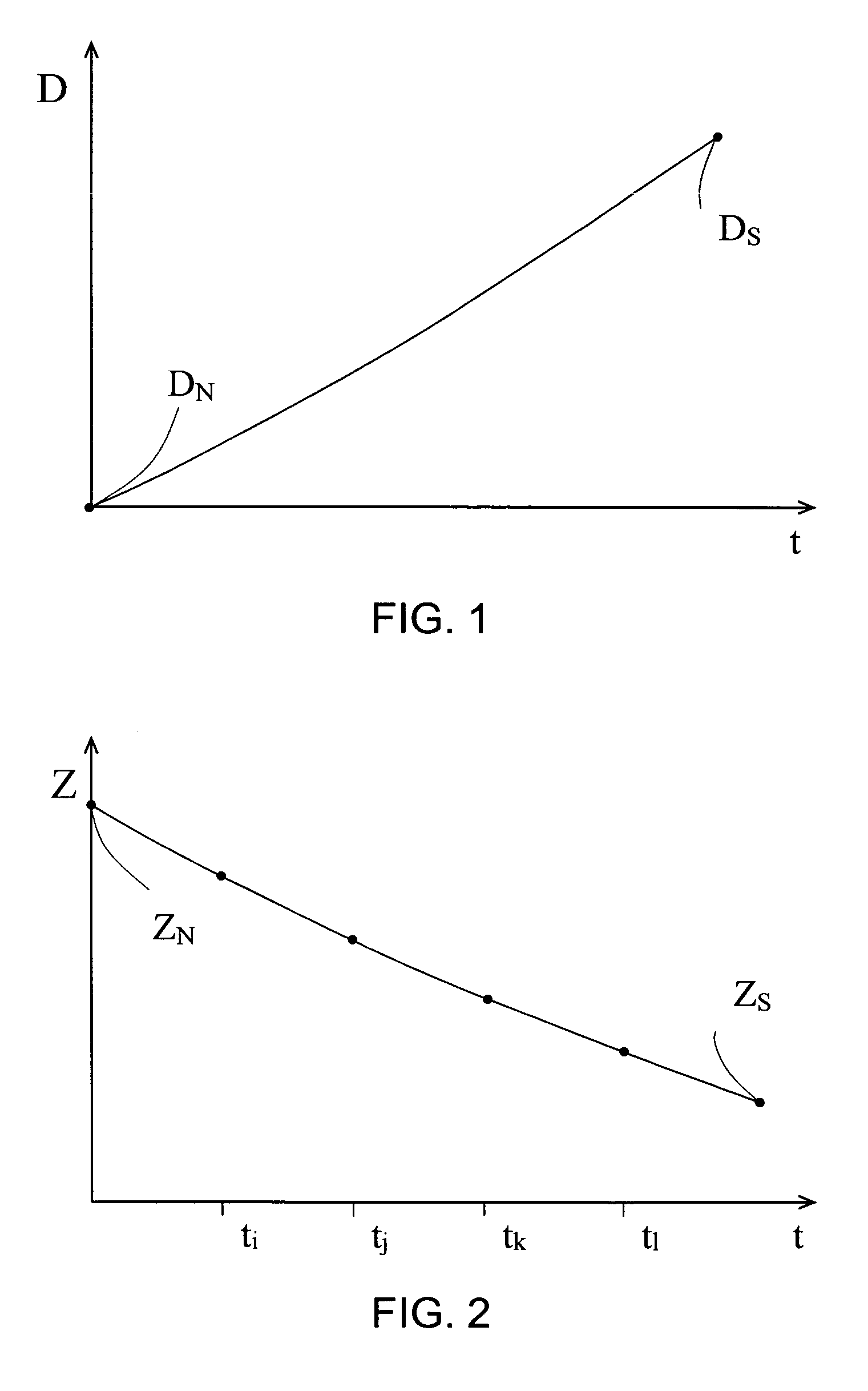
This results in a temperature compensated electrical property of the sensing capacitor, which represents the oil deterioration.

Method used


Image

  • Sensor and method for detecting oil deterioration and oil level
  • Sensor and method for detecting oil deterioration and oil level
  • Sensor and method for detecting oil deterioration and oil level

Examples


examples

[0256]The following are examples and experimental information of the present invention, regarding the capacitive sensor having the integrated plated electrodes operated by an AC voltage of a single frequency to test samples of lubricating oil, which are offered by way of illustration only and not by way of limitation and restriction.

[0257]A sensing capacitive sensor was constructed with three identical plates of a copper alloy serving as the respective electrodes. Each metal plate had a thickness of approximately 1 mm and the shape of a table tennis bat, including a bottom rectangular section connected to a top longitudinal bar having a top end serving as the top end of the plate, wherein the bar is aligned with a longitudinal central line of the rectangular section. Obviously the rectangular section provided effective surface areas of the sensor, and the bar served as an electrical connecting means and mechanical supporting means to connect and support the bottom section. Therefore...


PUM

PropertyMeasurementUnit
frequencyaaaaaaaaaa
alternating current analyzing deviceaaaaaaaaaa
thicknessaaaaaaaaaa

Abstract

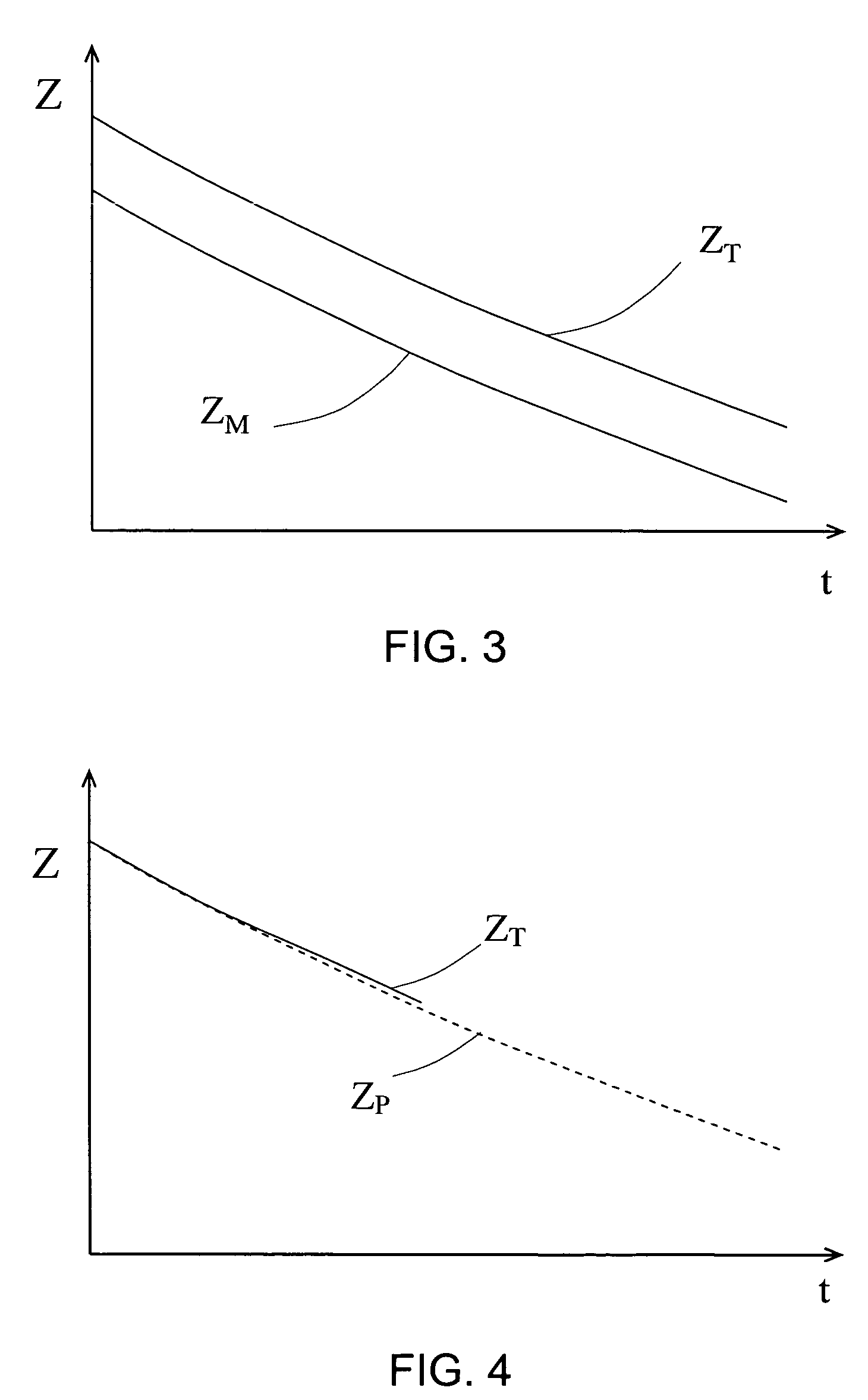
A capacitive sensor in its simplest form has three identical plated spatial electrodes, which are positioned equally spaced apart, in order, alignment and parallel with each other. The first and third electrodes are the outer electrodes and connected in parallel by a first lead wire serving as a first electrical pole to be a group of the integrated electrodes. The second electrode is the middle electrode and connected by a second lead wire serving as a second electrical pole. The sensor is applied with an alternating current (AC) excitation signal from an AC device. The present invention method includes application of referencing and sensing capacitive sensors to obtain a measured temperature compensated electrical property of the oil to thereby obtain a measured remaining usage so as to a predicted remaining usage of the oil. Therefore, the top oil level, or the normal, or the abnormal oil deterioration can be concluded according to the measured remaining usage which is respectively larger than, or similar to, or less than the predicted one of the oil.

Description

CROSS-REFERENCE TO RELATED APPLICATIONS[0001]This application is a continuation-in-part of U.S. patent application Ser. No. 11 / 899,320 filed on Sep. 5, 2007, now U.S. Pat. No. 7,729,870.BACKGROUND OF THE INVENTION[0002]1. Field of the Invention[0003]The present invention is generally related to oil which is used in machinery such as internal combustion engines and electrical transformers, and more particularly related to sensor and method for the on-line detection of the oil level, and the oil deterioration which occurs in the presence or absence of water.[0004]2. Description of the Prior Art[0005]Sensors and methods for detecting oil deterioration and oil level are well known. The following 21 patents and published patent applications are the closest prior art references which are related to the present invention.[0006]1. U.S. Pat. No. 4,517,547 issued to Gary et al. on May 14, 1985 for “Water-In-Fuel Sensor Circuit And Method” (hereafter the “Gary Patent”);[0007]2. U.S. Pat. No. 4...

Claims


Application Information

Patent Timeline
Patent Type & Authority Patents(United States)
IPC IPC(8): G01F17/00G01F23/00G01K13/00
CPCG01F23/265G01N33/2847G01N33/2888
Inventor SUN, YIZHONG
Owner SUN YIZHONG
Learn More