
Method for forming ceramic layer having garnet crystal structure phase and article made thereby

a technology of garnet crystal structure and ceramic layer, which is applied in the field of forming ceramic layer having garnet crystal structure phase and making articles thereby, can solve the problems of difficult to form large, dense ceramic components, and difficult to fabricate large ceramic components from a uniform or monolithic ceramic composition

Inactive Publication Date: 2005-04-26
SAINT GOBAIN CERAMICS & PLASTICS INC
View PDF16 Cites 34 Cited by
  • Summary
  • Abstract
  • Description
  • Claims
  • Application Information

AI Technical Summary

Benefits of technology

[0010]In one aspect of the present invention, a method is provided for depositing a coating on a substrate. In this method, a ceramic powder including a garnet crystal structure phase is thermally sprayed onto the substrate thereby forming a desired coating. The coating includes the garnet crystal structure phase. In another aspect of the invention, an article is provided including a substrate and a garnet crystal structure coating overlying the

Problems solved by technology

Such problems are especially acute in semiconductor processing.
Silicon wafers are typically etched in reactors using halogen radicals that are extremely corrosive.
As is understood in the art, it is generally difficult to fabricate large ceramic components from a uniform or monolithic ceramic composition.
In particular, it is generally difficult to form large, dense ceramic components, as thermal stresses and non-uniformities tend to produce cracking in the component.
However, this technique suffers from several disadvantages.
For example, the sputtering technique cannot produce robust coatings having a thickness greater that about 5 microns, which thickness is generally desirable for corrosion protection.
In particular, the process is slow and expensive, and thick coatings generally delaminate from underlying substrate due to internal residual stresses in the coating.
While the foregoing thermal spray process provides significantly higher deposition rates than the above-described sputtering process, the secondary heat treatment step to effect phase transformation of the deposited coating is problematic.
In particular, the temperatures at which the heat treatment step is executed have a tendency to damage or affect the structural integrity of certain types of underlying substrates such as aluminum-based alloys.

Method used


Image

  • Method for forming ceramic layer having garnet crystal structure phase and article made thereby
  • Method for forming ceramic layer having garnet crystal structure phase and article made thereby
  • Method for forming ceramic layer having garnet crystal structure phase and article made thereby

Examples


example 1

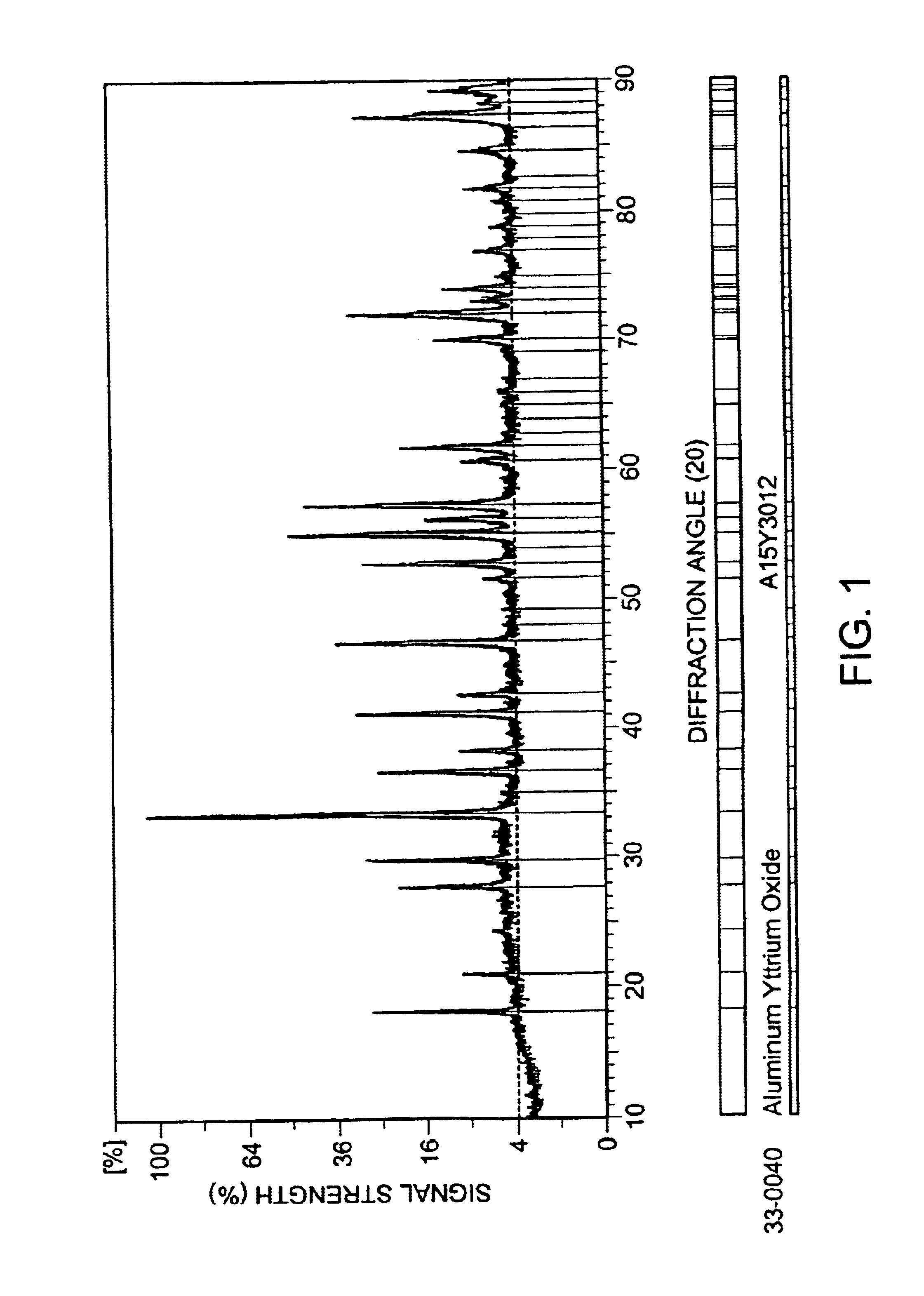
[0035]A commercially available stoichiometrically accurate yttrium aluminum garnet powder having a nominal particle size within a range of about 5 to about 45 microns was fed to a plasma torch according to the general conditions described above. The plasma torch was held at a level of 37.4 kW. Thermal spraying was carried out on an alumina substrate that was not preheated. The plasma spray was quenched by air blowing.

example 2

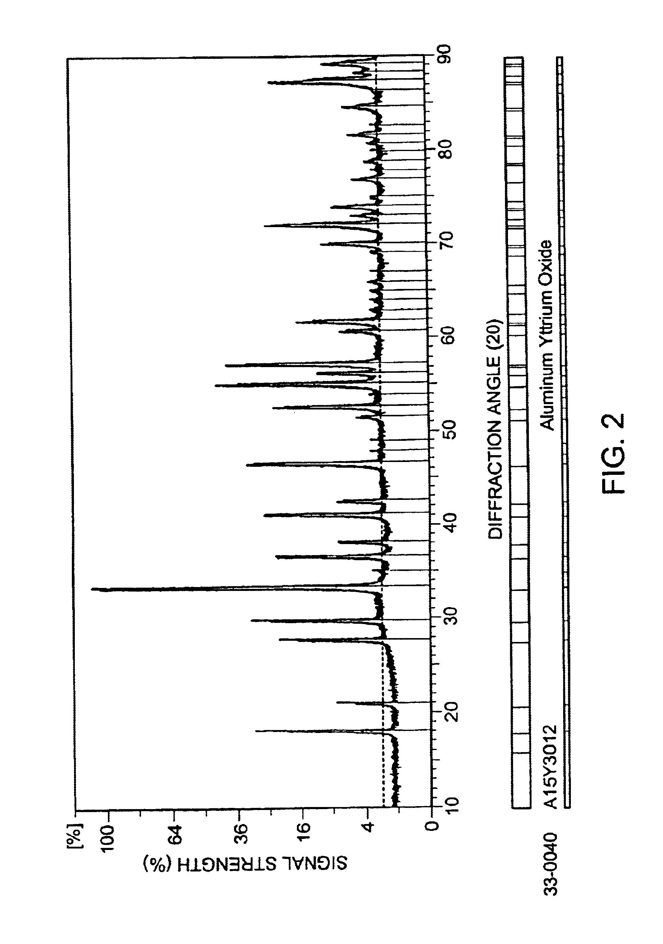
[0036]Example 2 was prepared in the same manner as example 1, except that the substrate was preheated at a temperature of about 220° C., the plasma torch was held at a power level of 34.1 kW, and the plasma spray was quenched via implementation of a gas barrier.

example 3

[0037]Example 3 as prepared in a manner identical to example 1, except that the ceramic powder had a slightly shifted yttrium content, particularly, the powder was rich in yttrium by an amount of two percent by mass. The particles size of this powder was within a range of about 10 to about 63 microns.


PUM

PropertyMeasurementUnit
Fractionaaaaaaaaaa
Thicknessaaaaaaaaaa
Thicknessaaaaaaaaaa

Abstract

A method of depositing a coating is disclosed, which method calls for providing a substrate, and thermally spraying a ceramic powder thereon to form a coating. The ceramic powder has a garnet crystal structure phase, and the thermal spraying in turn forms a coating on the substrate that includes a garnet crystal structure phase.

Description

CROSS-REFERENCE TO RELATED APPLICATION(S)BACKGROUND[0001]1. Field of the Invention[0002]The present invention relates generally to methods for depositing a coating on a substrate, and more particularly, to methods for depositing a coating by using a thermal spraying technique to form a coating having a garnet crystal structure phase.[0003]2. Description of the Related Art[0004]Ceramic materials having the garnet crystal structure, such as rare-earth aluminates, have been identified as potential materials in various industry applications, and have been of particular interest in industry areas ranging from semiconductor processing to aircraft and land-based turbine engine fabrication. In particular, garnet structured ceramic materials have been identified as having useful properties, including high-temperature strength, such as at elevated temperatures on the order of 1300° C. and higher. In addition, garnet ceramics are resistant to corrosion from reactive materials such halogens and...

Claims


Application Information

Patent Timeline
IPC IPC(8): C23C4/10
CPCC23C4/105H01J37/321Y10T428/26C23C4/11C23C4/134
Inventor SIMPSON, MATTHEW A.BILLIERES, DOMINIQUEMAIN, GERARDDROUIN, JEAN-MICHEL
Owner SAINT GOBAIN CERAMICS & PLASTICS INC
Learn More