
Method of injection molding of thermoplastic resin

Inactive Publication Date: 2005-04-26
ASAHI KASEI KK
View PDF12 Cites 15 Cited by
  • Summary
  • Abstract
  • Description
  • Claims
  • Application Information

AI Technical Summary

Benefits of technology

[0054]The molding method of the invention is applicable to the molding of molded articles that are similar to common non-foamed molded articles and the effectiveness of the invention is noticeable in thin-walled molded articles, moldings of unequal section thickness having both a thick-walled portion and a thin-walled portion in one part, and moldings having large flow distance from the gate. In order to ensure that the effectiveness of the invention is noticeable, moldings of unequal section thickness are preferred that are not more than 2 mm thick in the thin-walled portion and which are at least twice as thick in the thick-walled portion as in the thin-walled portion and more preferred are moldings of unequal section thickness that are not more than 2 mm thick in the thin-walled portion and which are at least three times as thick in the thick-walled portion as in the thin-walled portion. The section thickness as mentioned here means the thickness of a plate or a ribbed portion and it means the diameter of a cylindrical part such as a boss.
[0055]Carbon dioxide is used in the invention as a substance that is incorporated in thermoplastic resins to work as a plasticizer to lower their melt viscosity. Carbon dioxide has many advantages such as high solubility in molten resin, no deterioration of the resin, mold and the constituent material of the molding machine, no hazard to the environment in which molding is performed, low cost, and rapid evaporation from the molded article after molding. It should be noted that in the invention, carbon dioxide may be used either alone or in combination with hydrocarbons of 1 to 5 carbon atoms and / or Freons prepared by replacing some of the hydrogen atoms in those hydrocarbons with fluorine, or liquids such as water and alcohols.
[0056]The amount of carbon dioxide in the molten resin with which the mold cavity is to be filled is difficult to measure directly, so in the invention, the difference between the weight of a molded article measured immediately after injection molding of a carbon dioxide containing resin and the weight of the molded article measured after leaving it to stand for 24 hours in the atmosphere, then for at least 24 hours in a vacuum dryer at a temperature about 30° C. lower than the glass transition temperature of the resin if it is an amorphous resin or the melting point of the resin if it is a crystalline resin, until the amount of the carbon dioxide contained in the molded article has leveled off as a result of dissipation is defined as the amount of the carbon dioxide in the molten resin injected into the mold cavity.
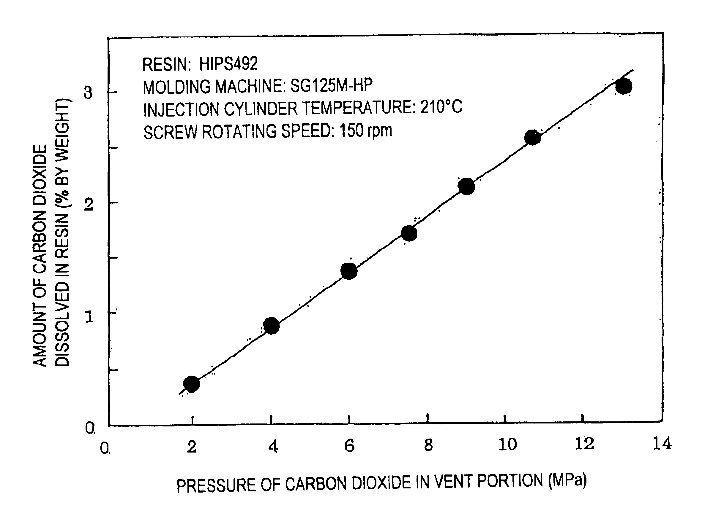
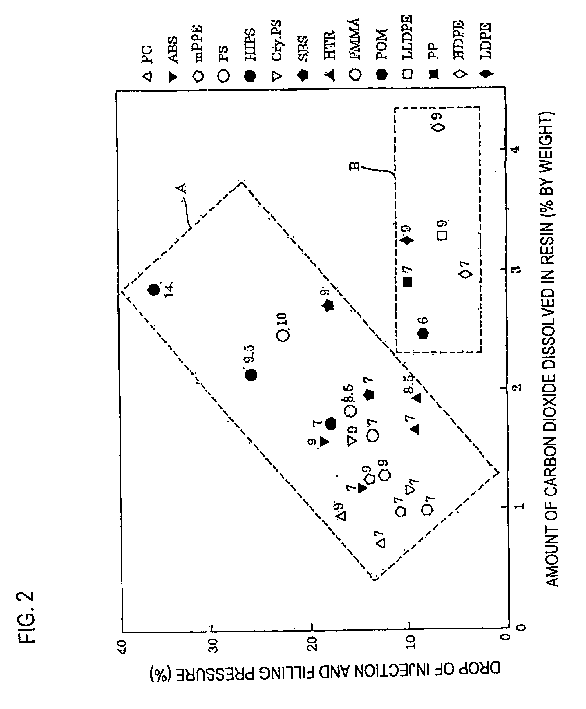
[0057]Carbon dioxide dissolves well in thermoplastic resins to become a good plasticizer that improves the flowability of the thermoplastic resins. In the invention, carbon dioxide is dissolved in an amount of at least 0.2 wt % in molten thermoplastic resins. In order to achieve marked improvement in flowability, at least 0.2 wt % of carbon dioxide is necessary and at least 0.3 wt % is preferred. There is no particular limitation on the maximum amount by which carbon dioxide can be dissolved; however, high gas pressure is needed in order to dissolve a large amount of carbon dioxide and an undue increase in the amount of dissolution simply reduces the effectiveness of carbon dioxide in improving the flowability of the resin; hence, a practical amount of carbon dioxide that may be dissolved is 10 wt % or less, more preferably 5 wt % or less.
[0058]The following are two preferred methods for dissolving carbon dioxide in thermoplastic resins.
[0059]In one method, a particulate or powdery resin is preliminarily placed in a carbon dioxide atmosphere and after allowing it to absorb carbon dioxide, the resin is fed into the molding machine. In this case, the amount of carbon dioxide absorption is determined by its pressure, the temperature of its atmosphere and the time of absorption. In this method, part of the carbon dioxide in the resin evaporates as it is heated during plasticization, so the amount of carbon dioxide in the molten resin is smaller than the preliminarily absorbed dose. Hence, it is desirable that the resin feed path such as the hopper in the molding machine is also held in a carbon dioxide atmosphere, optionally pressurized up to a value close to the pressure for absorption.

Problems solved by technology

The demand for smaller thickness and lighter weight is not limited to the housings of mobile electronic devices such as portable computers and cell phones and it has recently become intensive in the field of general electronic devices.
Thermoplastic resins have high melt viscosity and are poor in flowability as molding materials.
Hence, in the case of thin-walled parts, incomplete resin filling often occurs.
In order to lower the viscosity of a molten resin and thereby improve the flowability, it is effective to increase the molding temperature; however, in the case of a resin for which the molding temperature is close to its decomposition temperature or a resin incorporating special additives such as less heat-stable flame retardants, the resin itself or the additives may undergo thermal decomposition and problems are likely to occur as exemplified by the decrease in the strength of moldings, the formation of foreign matter due to the deteriorated resin, the staining of the mold and discoloration.
Yet another problem is delayed cooling of the resin in the mold which contributes to prolonging the molding cycle time.
However, the aforementioned method (1) lowers impact strength and chemical resistance although it increases flowability; the aforementioned method (2) lowers hot rigidity; and the aforementioned method (3) has problems such as the plasticizer lowering hot rigidity or being deposited on the mold to stain it during molding.
The aforementioned method (4) has the advantage of not causing the problems encountered in the above methods (1)-(3); however, since the gas incorporated in the molten resin also functions as a blowing agent, this method suffers the problem that the molded article tends to have a foam structure.
In this method described in the official gazette of Japanese Patent Laid-Open No. 318541 / 1993, the above-mentioned rapid breathing cannot be effected if more gas is incorporated in the molten resin and this sets considerable limit to the volume of the gas that can be preliminarily incorporated in the molten resin.
Specifically, if carbon dioxide is used as gas in the method described in the official gazette of Japanese Patent Laid-Open No. 318541 / 1993, the amount of carbon dioxide that can be dissolved in the molten resin is as small as about 0.18 wt % at maximum and this is insufficient to achieve the satisfactory improvement in flowability.
Under these circumstances, the present inventors proposed in WO 98 / 52734 a new method of injection molding which used carbon dioxide as a plasticizer but it still suffered the problem of difficulty in achieving the satisfactory improvement in flowability.

Method used


Image

  • Method of injection molding of thermoplastic resin
  • Method of injection molding of thermoplastic resin
  • Method of injection molding of thermoplastic resin

Examples


example 1

[0103]The polycarbonate as a resin feed was plasticized in the plasticizing cylinder as it was supplied with carbon dioxide, whereby carbon dioxide was dissolved in the molten resin.

[0104]For this molten resin, the resin pressure within the plasticizing cylinder that was necessary for resin filling was measured at a mold surface temperature of 80° C. Given a filling time of 0.6 seconds, the required filling pressure was 220 MPa. The resin filling was followed by 3-second dwelling at a pressure of 190 MPa within the plasticizing cylinder and, after 20-second cooling, the molded article was removed and examined with the naked eye.

[0105]The molded article had swirl marks on the surface but no sink marks were found on the side opposite the rib, nor was found any warpage. A cross section of the molded article was also examined and no bubbles were found.

example 2

[0106]As in Example 1, the resin pressure within the plasticizing cylinder that was necessary for resin filling was measured for the rubber-reinforced polystyrene at a mold surface temperature of 40° C.; the required filling pressure was 150 MPa. The resin filling was followed by 3-second dwelling at a pressure of 120 MPa within the plasticizing cylinder and, after 20-second cooling, the molded article was removed and examined with the naked eye.

[0107]The molded article had swirl marks on the surface but no sink marks were found on the side opposite the rib, nor was found any warpage. A cross-sectional examination showed no presence of bubbles.

example 3

[0108]As in Example 1, the resin pressure within the plasticizing cylinder that was necessary for resin filling was measured for the modified poly(phenylene ether) resin at a mold surface temperature of 90° C.; the required filling pressure was 210 MPa. The resin filling was followed by 3-second dwelling at a pressure of 180 MPa within the plasticizing cylinder and, after 20-second cooling, the molded article was removed and examined with the naked eye.

[0109]The molded article had swirl marks on the surface but no sink marks were found on the side opposite the rib, nor was found any warpage. A cross-sectional examination showed no presence of bubbles.


PUM

PropertyMeasurementUnit
Temperatureaaaaaaaaaa

Abstract

The invention is to ensure that in injection molding a molten resin having carbon dioxide dissolved therein as a plasticizer, a sufficient amount of carbon dioxide to achieve satisfactory improvement in flowability is dissolved in the molten resin so that the flowability of the molten resin is significantly improved while enabling the production of a non-foamed molded article.Specifically, in the invention, a molten resin having dissolved therein a sufficient amount of carbon dioxide to improve its flowability is filled into a mold cavity while allowing to foam at the flow front of the molten resin, and the resin in the mold cavity is then pressurized to at least a pressure at which it does not foam.

Description

[0001]This application is the national phase under 35 U.S.C. §371 of PCT International Application No. PCT / JP01 / 04598 which has an International filing date of Jun. 12, 2001, which designated the United States of America.TECHNICAL FIELD[0002]This invention relates to a method of injection molding of a thermoplastic resin, and more specifically, to a method of injection molding that provides ease in filling a mold cavity with a molten resin and which enables sections of a smaller wall thickness and a longer flow distance to be filled with a molten resin at a lower temperature or pressure.BACKGROUND ART[0003]The demand for smaller thickness and lighter weight is not limited to the housings of mobile electronic devices such as portable computers and cell phones and it has recently become intensive in the field of general electronic devices. In particular, the chassis and the internal mechanistic parts of a copying machine and the like are required to have not only high dimensional prec...

Claims


Application Information

Patent Timeline
IPC IPC(8): B29C45/00B29C45/17B29C45/18
CPCB29C45/00B29C45/1701B29C45/1816B29C2045/1702B29C2043/527
Inventor YAMAKI, HIROSHI
Owner ASAHI KASEI KK
Learn More