
Apparatus for pre-treatment and subsequent plastification or agglomeration of synthetic plastic materials

a technology of synthetic plastic materials and apparatuses, which is applied in the field of apparatuses for pretreatment and subsequent plastification or agglomeration can solve the problems of affecting the molecule chain of synthetic plastic materials, processing materials are subjected to higher mechanical and thermical stresses, and the quality of the known constructions is not met, so as to achieve constant material quality, the effect of reducing the temperature profile of the extruder and ensuring the quality of the material

Inactive Publication Date: 2005-04-26
BACHER HELMUT +2
View PDF14 Cites 32 Cited by
  • Summary
  • Abstract
  • Description
  • Claims
  • Application Information

AI Technical Summary

Benefits of technology

[0012]Accordingly, it is an object of the invention to overcome these disadvantages and to improve an apparatus of the initially described kind so that this apparatus can be operated with a higher screw output, at a constant material quality, or, respectively, that, when keeping the screw output constant, the temperature profile of the extruder can be kept substantially lower, for example up to 20° C. lower, which means power saving and a better quality of the material obtained.
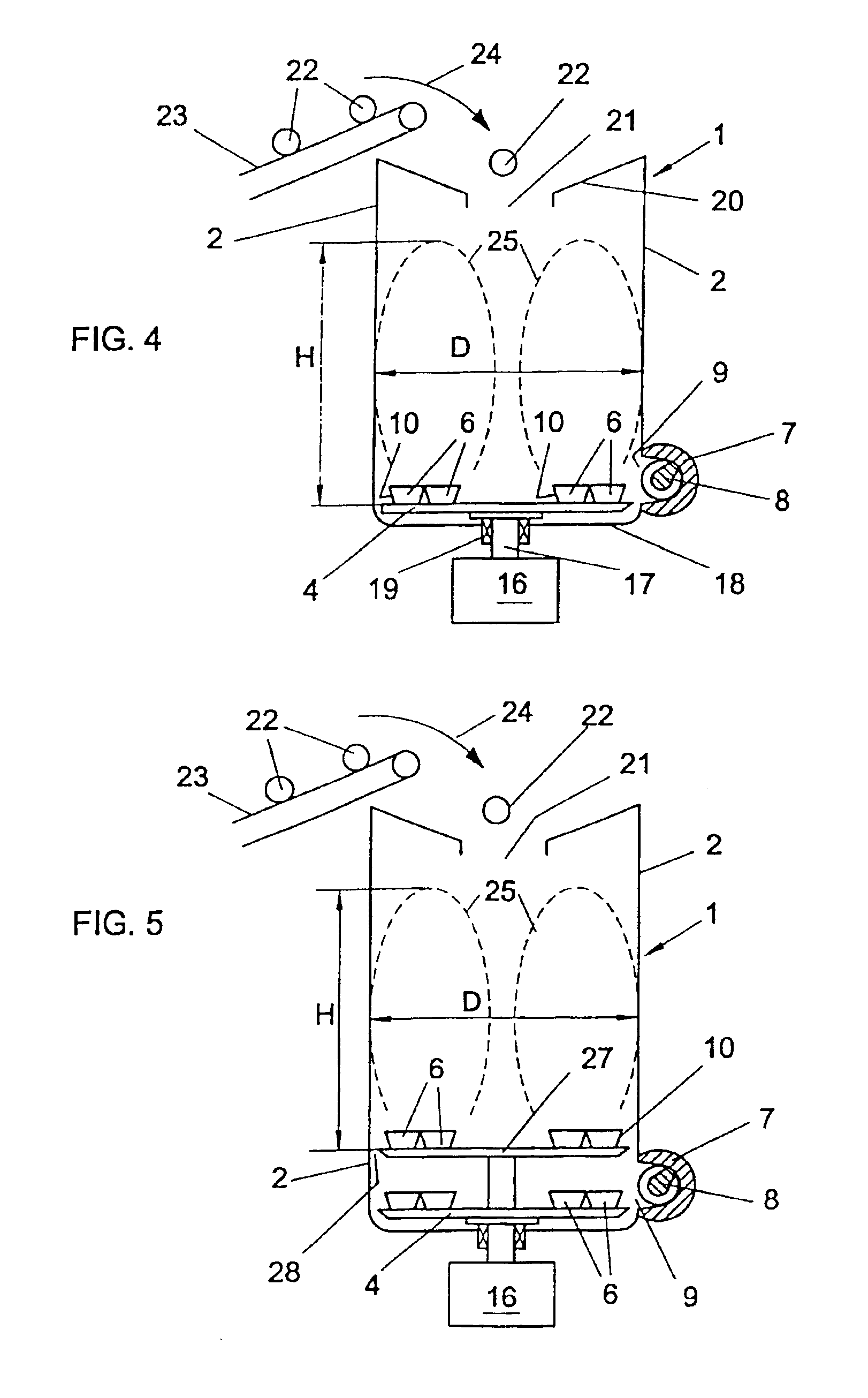
[0018]By the increase of the receptacle (mostly a shredder receptacle), when compared with usual sizes, it is found that the mechanical and thermic homogeneity of the synthetic plastic material pre-processed within the receptacle is made more uniform, even if this material is difficult to process. The reason for this is that the mass ratio between the constantly supplied unprocessed “cold” material portions and the material mass present within the container and already partially treated is lower when compared with the usually occurring conditions, and that the main dwell time of the synthetic plastic material within the container is substantially increased. This decrease of the mass ratio has a favorable influence upon the thermic and mechanical homogeneity of the material entering the screw housing from the container and, therefore, directly upon the quality of the plastificate or of the agglomerate at the end of the extruder screw or of the agglomerating screw, because the theoretical dwell time of the processed synthetic plastic material within the container becomes substantially constant. Further, such a plant having an increased receptacle can be more easily operated with respect to the exactness of the supplied portions when compared with the known plants.
[0031]If value is set on an additional increase of the output or on an improved capacity of the shredder-extruder combination, then, within extruders of the same size, therefore, with a screw diameter of the same size, the depth of the screw volution can be increased and the speed of the screw can be increased without the processed material being subjected to an increased shearing action within the screw. This means also that the mass temperature of the plastificate and, therefore, also the entire power consumption for processing is decreased. In particular when processing thermically unstable thermoplasts, this is of importance. Therefore, the use of an increased receptacle volume enables one not only to increase the output of the shredder-extruder combination by more than 50%, when compared with constructions usual heretofore, but also to considerably save power. For example, the enthalpy-curve of polyethylene having a density of 0.92 g / cm3 shows a saving of melting power (at a processing temperature decreased for 20° C.) of 25 W / kg, i.e. almost a 14.5% power saving.
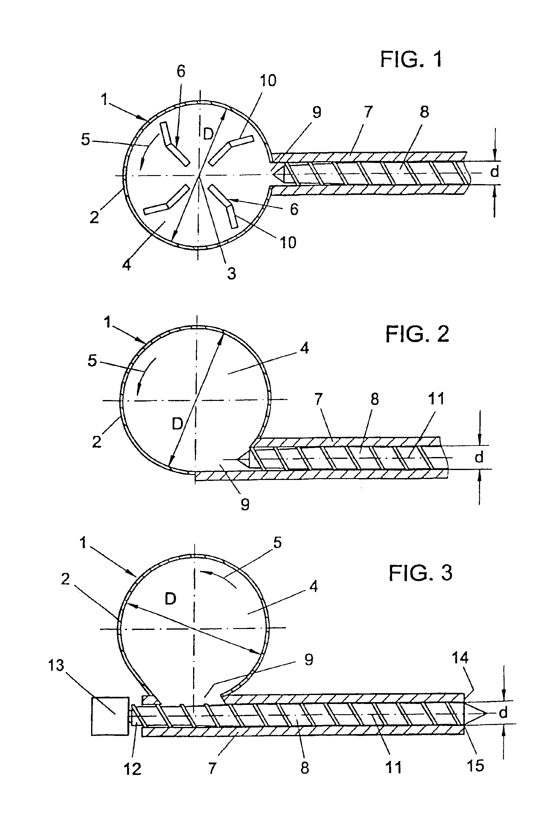
[0035]In an analogous manner, the depth of the volutions of the screw cannot be increased at will, because the remaining core diameter of the screw must be able to take up the torque applied to the screw. Within this, problems may arise with a construction in which the axis of the screw is disposed tangentially with respect to the cross-section of the receptacle, the housing of the screw having in its side wall an intake opening for the material that has to be taken up by the screw, the screw on its one front end being connected to a drive means and on its other front end conveying towards an exit opening, in particular an extruder head, disposed at the front end of the screw housing. With such a construction, of course, it is desired to keep the depth of volutions of the screw within the region of the intake opening of the screw housing as great as possible in order to improve the intake behavior of the screw. This, however, is limited by the grounds mentioned above. Within the spirit of the invention, however, there is the possibility to correspond to these demands that are in contradiction to each other by a special construction. This construction consists in that the screw housing in the region of its intake opening forms a pocket constituting an additional free space for synthetic plastic material that has to be introduced into the screw housing, wherein at that edge of the intake opening at which the direction of rotation of the screw is directed towards the connected receptacle, a preferably adjustable rib is provided which closes this pocket entirely or partially with respect to the intake opening. In this manner, namely despite the reduced volution depth of the screw, a better intake behavior of the screw can be obtained.
[0036]However, within the spirit of the invention it is also possible to dispose the axis of the screw radially or like a secant with respect to the cross-section of the receptacle, for example within agglomerating apparatus in which the volution depth of the screw decreases towards the exit opening of the screw housing. As is well known, agglomerating apparatus, when compared with plasticizing apparatus, have a reduced screw length. The volution geometry of an agglomerating screw differs from the volution geometry of a plasticizing screw. The agglomerating screw in the region of the intake zone and in the region of the central zone adjoining it has an increased volution depth, when compared to usual plasticizing screws. Only in the region of the dosing metering zone is the volution depth of the agglomerating screw low, so that the material is intensely compressed and subjected to a shearing action only in the region of the metering zone and, therefore, only for a short time without being plasticized. The agglomerating screw, therefore, delivers on its exit material which is not completely plasticized, but consists of particles melted only at their surface, which particles in the manner of a sintering action adhere to each other.

Problems solved by technology

Most of these known constructions do not meet the requirements with respect to the quality of the processed synthetic plastic material obtained at the exit of the screw and / or with respect to the yield of the screw.
These deviations can be caused by different properties of the material batches introduced step by step into the receptacle, for example different quality or different thickness of the synthetic plastic material, for example foil rests and the like, however, also by uncontrollable random events.
However, the processed material is thereby subjected to higher mechanical and thermical stresses by the screw; i.e. there is the danger that the molecule chains of the synthetic plastic material are adversely affected.
As a further disadvantage, there occurs more wear of the screw and its housing, in particular when processing recycling material due to the impurities contained within this material, for example abrasive particles, metal pieces or the like, which have a high wear effect on the metal elements of the screw and its bearings sliding along each other.
With a slowly rotating and deeply cut screw (great depth of the volutions) as well as with a quickly rotating screw, the already mentioned different quality of the single material batches supplied to the screw, for example different flake sizes and / or different temperature of the synthetic plastic material, have an adverse effect in view of inhomogeneities of the synthetic plastic material at the screw exit.
In order to equalize these inhomogeneities, in practice, the temperature profile of the extruder is increased, and this means that additional power must be supplied to the synthetic plastic material, which has as a result the mentioned thermic damages of the synthetic plastic material and an increased power consumption.
Further, the viscosity of the plastic material obtained at the extruder exit is reduced thereby, so that this material is very fluid, which causes difficulties when further processing this material.

Method used


Image

  • Apparatus for pre-treatment and subsequent plastification or agglomeration of synthetic plastic materials
  • Apparatus for pre-treatment and subsequent plastification or agglomeration of synthetic plastic materials
  • Apparatus for pre-treatment and subsequent plastification or agglomeration of synthetic plastic materials

Examples


Embodiment Construction

[0045]The drawings, for space reasons, are not true to scale, because in reality the receptacles are always much bigger than they are shown in the drawing.

[0046]In the embodiment according to FIG. 1 the apparatus, forming a shredder-extruder combination, comprises a receptacle 1 having a circular cross-section, the side wall 2 of it being substantially cylindrical. Within the receptacle 1 a carrier disc 4 rotates around a central vertical axis 3, which disc is driven from below by a drive means (not shown) so that it rotates in the direction of the arrow 5. The carrier disc 4 is disposed in the bottom region of the receptacle 1 and carries on its top surface a plurality of comminuting and mixing tools 6 acting on the synthetic plastic material to be processed, which is introduced into the receptacle from above, as a rule thermoplastic recycling material, in a comminuting and mixing manner. Substantially at the level of these circulating tools 6, the housing 7 of a screw 8 is radiall...


PUM

PropertyMeasurementUnit
temperatureaaaaaaaaaa
dwell timeaaaaaaaaaa
heightaaaaaaaaaa

Abstract

An apparatus for pre-processing and subsequent plastification or agglomeration of synthetic plastic materials, in particular thermoplastic waste plastics for recycling purposes, has a receptacle (1) in which at least one comminuting tool (6) circulates. The housing (7) of a screw (8) is connected to the receptacle (1). The diameter (D) of the receptacle (1) has the following relationship to the screw diameter (d):D=10.{square root over (K.d2)}, wherein D is the inner diameter of the receptacle in mm,d is the screw diameter in mm andK is a dimension-less constant which amounts to at least 190.Thereby the dwell times of the synthetic plastic material within the receptacle (1) are kept at optimal values.

Description

BACKGROUND OF THE INVENTION[0004]The invention refers to an apparatus for pre-treatment and subsequent plastification or agglomeration of synthetic plastic materials, in particular thermoplastic waste plastics for recycling purposes, comprising a receptacle that has an intake opening for the material to be processed and in which at least one circulating comminuting and / or mixing tool is disposed, whereby the material processed within the receptacle is fed into the housing of a screw plasticizing or agglomerating this material, for example an extruder screw, which housing preferably is connected to the receptacle.[0005]Apparatus of this kind are known in many embodiments. The pre-treatment of the synthetic plastic material to be processed mostly is a comminuting action which, however, can be also replaced by or can be combined with mixing and / or drying and / or heating and / or crystallizing and / or densifying of the material. In most apparatus of this kind, the tools revolving within the...

Claims


Application Information

Patent Timeline
Patent Type & Authority Patents(United States)
IPC IPC(8): B29B17/00B29C47/10B29B7/42B29B17/04B29C31/00B29C48/03B29C48/29B29C48/53B29K105/26
CPCB29B17/0026B29C47/6018B29C47/385B29C47/1054B29B2017/048B29C47/0009B29C47/1063Y02W30/62B29C48/397B29C48/29B29C48/03B29C48/2888B29C48/53B29B17/00
Inventor BACHER, HELMUTSCHULZ, HELMUTHWENDELIN, GEORG
Owner BACHER HELMUT
Learn More