
Glow plug and method of manufacturing the same

a technology of glow plugs and plugs, which is applied in the field of glow plugs, can solve the problems of potential instability of electrical connections and impair the durability of ceramic heaters, and achieve the effects of suppressing an increase in contact resistance, and ensuring electrical connection and high reliability

Inactive Publication Date: 2005-04-19
NGK SPARK PLUG CO LTD
View PDF17 Cites 20 Cited by
  • Summary
  • Abstract
  • Description
  • Claims
  • Application Information

AI Technical Summary

Benefits of technology

[0005]An advantage of the present invention is a glow plug having ensured electrical connection and high reliability through suppressing an increase in contact resistance between an electric conductor and a metallic fitting member.
[0006]Another advantage of the present invention is a method of manufacturing a glow plug having ensured electrical connection and high reliability through suppressing an increase in contact resistance between an electric conductor and a metallic fitting member.
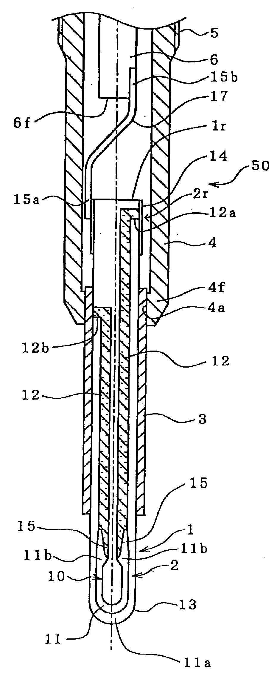
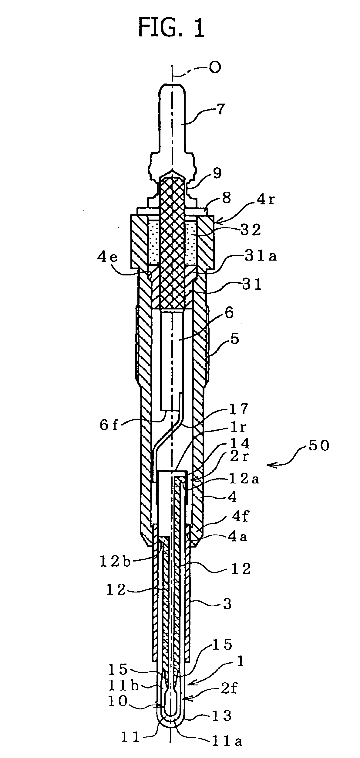
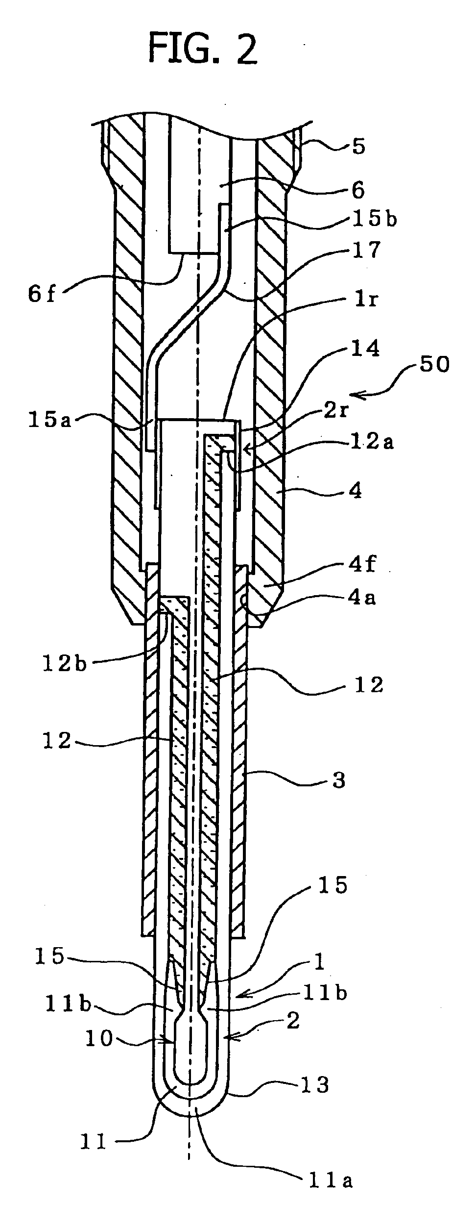
[0007]The present invention provides a glow plug comprising a ceramic heater assuming a rodlike form and having a resistance-heating element embedded in a distal end portion thereof; a first metallic fitting member externally joined to a rear end portion of the ceramic heater in such a manner as to surround an outer circumferential surface of the rear end portion; a second metallic fitting member disposed on a side toward a distal end of the ceramic heater in relation to the first metallic fitting member and externally joined to the ceramic heater in such a manner as to surround an outer circumferential surface of the ceramic heater; and a pair of electric conductors embedded in the ceramic heater so as to electrically connect the resistance-heating element and the first and second metallic fitting members. The electric conductors contain at least either W or Mo, one electric conductor has a first exposed portion joined to the first metallic fitting member, and the other electric conductor has a second exposed portion joined to the second metallic fitting member. In the glow plug, a metal layer not higher than Ni in ionization tendency is formed on an inner circumferential surface of the first metallic fitting member and on an inner circumferential surface of the second metallic fitting member, the inner circumferential surfaces facing the first and second exposed portions, respectively; and the metal layers are in contact with the corresponding first and second exposed portions such that an area of contact between the metal layer and the corresponding exposed portion is 30% or more of an area of the exposed portion.
[0008]The above-described glow plug of the present invention is characterized in that the metal layer not higher than Ni in ionization tendency is formed on the inner circumferential surface of each of the metallic fitting members. This feature smoothens the inner circumferential surfaces of the metallic fitting members, so that the metallic fitting members and the corresponding exposed portions of the electric conductors are mechanically joined together under such a smoothened surface condition. Therefore, electrical connection can be ensured at the joints between the metallic fitting members and the corresponding exposed portions. Since the metal layer is not higher than Ni in ionization tendency; i.e., has a sufficiently low reactivity with oxygen, oxidation of the exposed portions is prevented. In order to enhance the oxidation preventive effect, preferably, the metal layer is uniformly formed in an annular shape and is formed of a metal that does not react with high-temperature water vapor; i.e., is formed of a metal not higher than H in ionization tendency.
[0009]Furthermore, in the glow plug of the present invention, the metal layers and the corresponding exposed portions of the electric conductors are joined together such that an area of contact between the metal layer and the corresponding exposed portion is 30% or more of an area of the exposed portion. Thus, the metal layers and the corresponding exposed portions can be effectively joined together, and an increase in contact resistance can be suppressed, so that the glow plug can sufficiently exhibit required performance. When the area of contact is less than 30% of the area of the exposed portion, a portion of the metal layer that is not engaged in contact with the exposed portion of each electric conductor is oxidized in the course of repeated use of the glow plug. The oxidation propagates to a portion of the metal layer in contact with the exposed portion of each electric conductor, causing an increase in contact resistance. As a result, conduction of electricity to the heater becomes unreliable, resulting in a failure to provide a glow plug with high reliability.
[0010]Preferably, in the glow plug of the present invention, the metal layer has a thickness of 0.2 μm to 10 μm.

Problems solved by technology

However, this method involves a potential instability in electrical connection, since plating on the exposed portion is potentially scraped or exfoliated during a finish grinding process for the ceramic heater or a process of joining, for example, the ceramic heater and the metallic fitting members, or a ceramic heater assembly and the metallic shell.
Studies conducted by the present inventors have revealed that such dipping in the plating solution damages ceramic, thereby impairing durability of the ceramic heater.

Method used


Image

  • Glow plug and method of manufacturing the same
  • Glow plug and method of manufacturing the same
  • Glow plug and method of manufacturing the same

Examples


experimental example 1

[0061]The first and second terminal rings 14 and 3 were fabricated by use of SUS630. The first terminal rings 14 had the following dimensions: thickness: 0.25 mm; axial length: 0.5 mm to 6 mm (Experimental Example A: 6.0 mm; Experimental Example B: 2.8 mm; Experimental Example C: 2.2 mm; Experimental Example D: 1.3 mm; Experimental Example E: 0.8 mm; and Experimental Example F: 0.5 mm); and inside diameter d1: 3.4 mm. The second terminal rings 3 had the following dimensions: thickness: 0.85 mm; axial length: 20 mm; and inside diameter d1: 3.4 mm. An Ni strike plating layer was formed on the inner circumferential surfaces of the first and second terminal rings 14 and 3, which are to be fitted to the ceramic heater 1, by use of a known chloride bath. Subsequently, a Cu plating layer was formed on the Ni strike plating layer by use of a sulfate bath, thereby forming the metal layer 41 having a thickness of 3.2 μm.

[0062]The thus-fabricated second terminal ring 3 was fixed by use of a ji...

experimental example 2

[0068]Next, measurement similar to that of Experimental Example 1 was carried out for the case where Au, which is the lowest in ionization tendency, was plated on the inner circumferential surface of a metal fitting member. FIG. 10 also shows the measurement results (2A to 2F).

[0069]Comparison between the above measurement results and the test results of Experimental Example 1 reveals that the lower the ionization tendency of the metal layer 41, the greater the effect of suppressing an increase in contact resistance at a contact portion between the metal layer 41 and a heater terminal. As is apparent from FIG. 10, Ni and Ag (Ni: 3A to 3F; Ag: 4A to 4F), which are lower than Ni in ionization tendency, exhibit contact-resistance-increase-suppressing performance proportional to the degree of ionization tendency. Specifically, in comparison under the same conditions of use, the lower the ionization tendency, the longer the life; and even in use at higher temperatures, durability can be ...


PUM


Abstract

A glow plug includes a ceramic heater having a resistance-heating element embedded at its end portion. In order to supply electricity to the resistance-heating element, first and second heater terminals are exposed on the surface of the ceramic heater. First and second terminal rings, which serve as metallic fitting members, are shrink-fitted to the surface of the ceramic heater in such a manner as to cover and be electrically connected to the exposed first and second heater terminals. A metal layer not higher than Ni in ionization tendency is formed on the inner circumferential surface of each of the first and second terminal rings.

Description

FIELD OF THE INVENTION[0001]The present invention relates to a glow plug for preheating a diesel engine.BACKGROUND OF THE INVENTION[0002]Conventionally, a glow plug that has been widely used is configured such that a rodlike ceramic heater is disposed in a distal end portion of a tubular metallic shell with a distal end portion of the ceramic heater projecting from the distal end portion of the metallic shell. Current supplied to the ceramic heater flows along a route running through: a metallic rod disposed at a rear end portion of the metallic shell and connected to a power supply; a metallic lead element that connects the metallic rod and the ceramic heater; a first metallic fitting member; an electric conductor (including a conductive portion, a resistance-heating element, and a conductive portion) of the ceramic heater; a second metallic fitting member; the metallic shell; and an engine head. In a conventional glow plug, in order to suppress an increase in contact resistance, a...

Claims


Application Information

Patent Timeline
IPC IPC(8): F23Q7/00
CPCF23Q7/001F23Q2007/004
Inventor YOSHIKAWA, TAKAYAHOTTA, NOBUTUKIMURAKOSHI, SHINYASUZUKI, HIROYUKI
Owner NGK SPARK PLUG CO LTD
Learn More