
Micro-fabricated electrokinetic pump

a micro-fabricated, electrokinetic pump technology, applied in the direction of pump components, piston pumps, positive displacement liquid engines, etc., can solve the problems of increasing the operational pressure requirements of the pump, transient fluctuations, and difficulty in controlling the chip temperatur

Inactive Publication Date: 2005-04-19
VERTIV CORP
View PDF37 Cites 29 Cited by
  • Summary
  • Abstract
  • Description
  • Claims
  • Application Information

AI Technical Summary

Benefits of technology

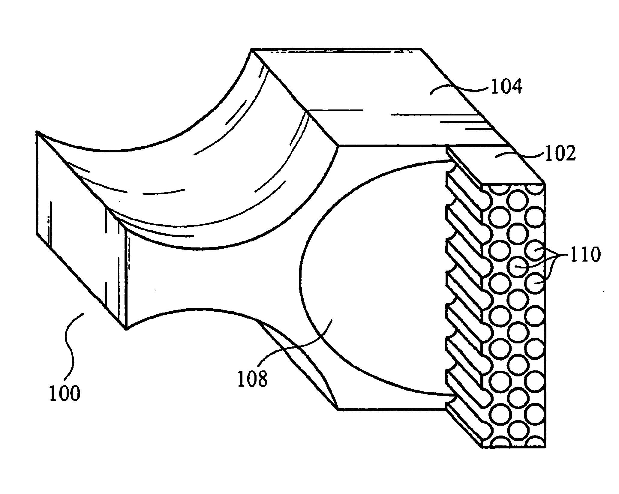
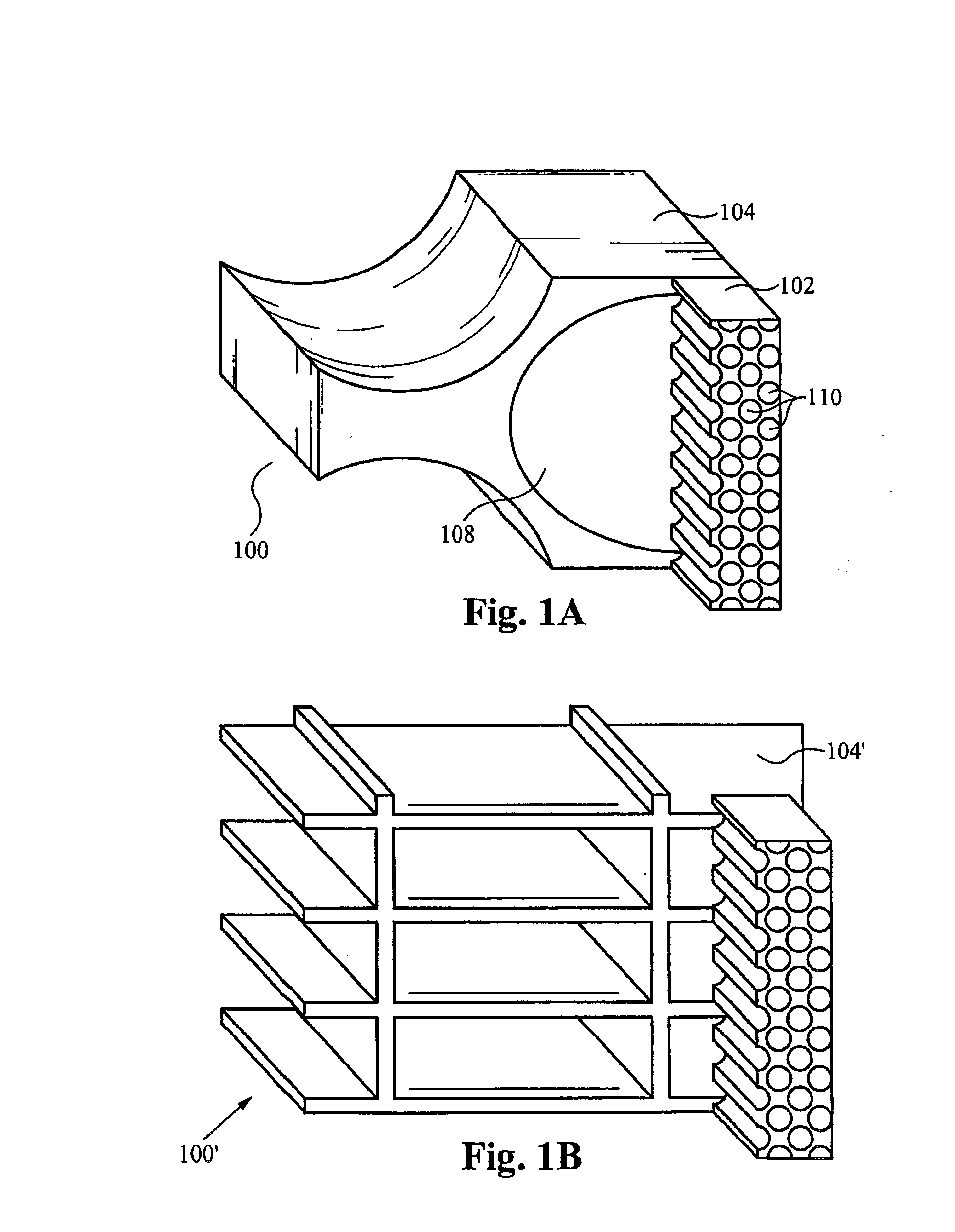
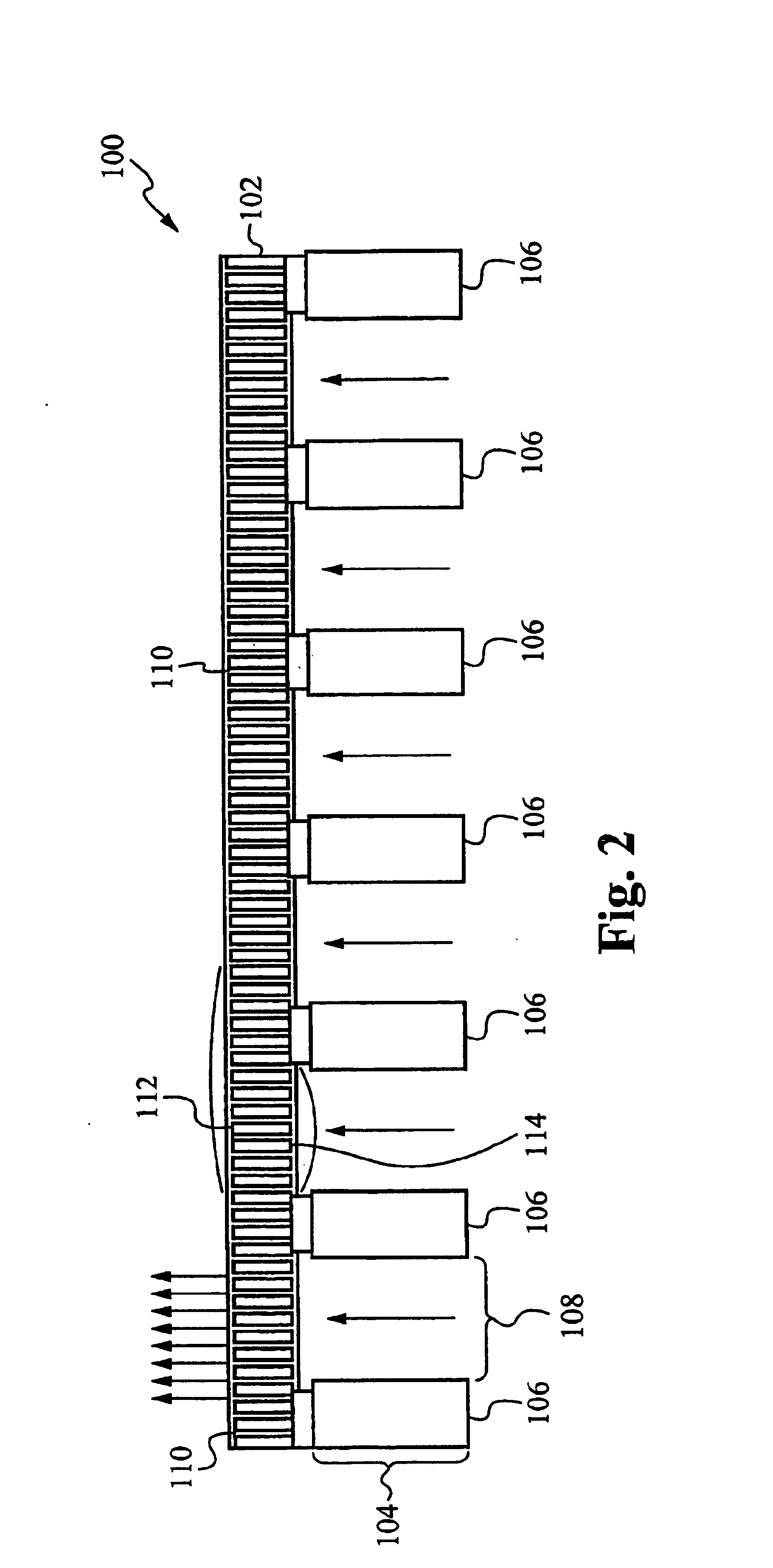
The patent describes an electrokinetic pump that can pump liquid using a voltage difference. The pump has a thin body with small pores that allow the liquid to flow through. The pump is made using semiconductor processing techniques and is supported by a support structure. The technical effects of this invention include a thin, efficient pump that can be easily fabricated using existing techniques. The pump can be used to move liquids in a controlled and reliable manner, which makes it useful in various applications such as medical devices and sensors.

Problems solved by technology

This demonstration was all carried out with liquid-vapor mixtures in the microchannel heat exchangers because there was insufficient liquid flow to capture all the generated heat without boiling.
Conversion of some fraction of the liquid to vapor imposes a need for high-pressure operation, and increases the operational pressure requirements for the pump.
Furthermore, two phase flow is less stable during the operation of a cooling device and can lead to transient fluctuations and difficulties in controlling the chip temperature.
A disadvantage of these structures is that the pore density, structure, and mean diameter is not uniform and also not easily reproduced in a low-cost manufacturing process.
Furthermore, the fluid path in these structures is highly tortuous, leading to lower flow rates for a given thickness of pump.

Method used


Image

  • Micro-fabricated electrokinetic pump
  • Micro-fabricated electrokinetic pump
  • Micro-fabricated electrokinetic pump

Examples


Embodiment Construction

[0036]Reference will now be made in detail to the preferred and alternative embodiments of the invention, examples of which are illustrated in the accompanying drawings. While the invention will be described in conjunction with the preferred embodiments, it will be understood that they are not intended to limit the invention to these embodiments. On the contrary, the invention is intended to cover alternatives, modifications and equivalents, which may be included within the spirit and scope of the invention was defined by the appended claims. Furthermore, in the following detailed description of the present invention, numerous specific details are set forth in order to provide a thorough understanding of the present invention. However, it should be noted that the present invention may be practiced without these specific details. In other instances, well known methods, procedures, components, and circuits have not been described in detail as not unnecessarily obscure aspects of the p...


PUM


Abstract

An electrokinetic pump for pumping a liquid includes a pumping body having a plurality of narrow, short and straight pore apertures for channeling the liquid through the body. A pair of electrodes for applying a voltage differential are formed on opposing surfaces of the pumping body at opposite ends of the pore apertures. The pumping body is formed on a support structure to maintain a mechanical integrity of the pumping body. The pump can be fabricated using conventional semiconductor processing steps. The pores are preferably formed using plasma etching. The structure is oxidized to insulate the structure and also narrow the pores. A support structure is formed by etching a substrate and removing an interface oxide layer. Electrodes are formed to apply a voltage potential across the pumping body. Another method of fabricating an electrokinetic pump includes providing etch stop alignment marks so that the etch step self-terminates.

Description

RELATED APPLICATION[0001]This Patent Application claims priority under 35 U.S.C. 119(e) of the co-pending U.S. Provisional Patent Application Ser. No. 60 / 413,194 filed Sep. 23, 2002, and entitled “MICRO-FABRICATED ELECTROKINETIC PUMP”. The Provisional Patent Application Ser. No. 60 / 413,194 filed Sep. 23, 2002, and entitled “MICRO-FABRICATED ELECTROKINETIC PUMP” is also hereby incorporated by reference.FIELD OF THE INVENTION[0002]The present invention relates to an apparatus for cooling and a method thereof. In particular, the apparatus is for an improved electrokinetic pump having substantially straight and very small pore apertures and lengths. The pump is manufactured by a process using semiconductor processing techniques.BACKGROUND OF THE INVENTION[0003]High density integrated circuits have evolved in recent years including increasing transistor density and clock speed. The result of this trend is an increase in the power density of modern microprocessors, and an emerging need fo...

Claims


Application Information

Patent Timeline
Patent Type & Authority Patents(United States)
IPC IPC(8): F04B17/00F04B19/00F04F99/00
CPCF04B19/006F04B17/00F04B37/02F04B43/04F04B43/043F04B43/09F04B19/00F04B23/00
Inventor CORBIN, DAVIDGOODSON, KENNETHKENNY, THOMASSANTIAGO, JUANZENG, SHULIN
Owner VERTIV CORP
Learn More