
Indoor GPS clock

a gps clock and indoor technology, applied in navigation instruments, instruments, horology, etc., can solve the problems of inability to accept limitations, inability to accurately calculate gps time, and inability to function well within a building, so as to achieve accurate gps-based frequency and time.

Inactive Publication Date: 2005-04-12
TRIMBLE NAVIGATION LTD
View PDF14 Cites 26 Cited by
  • Summary
  • Abstract
  • Description
  • Claims
  • Application Information

AI Technical Summary

Benefits of technology

It is therefore an object of the present invention to provide an indoor GPS clock capable of using low level GPS signals for providing accurate GPS-based frequency and time.
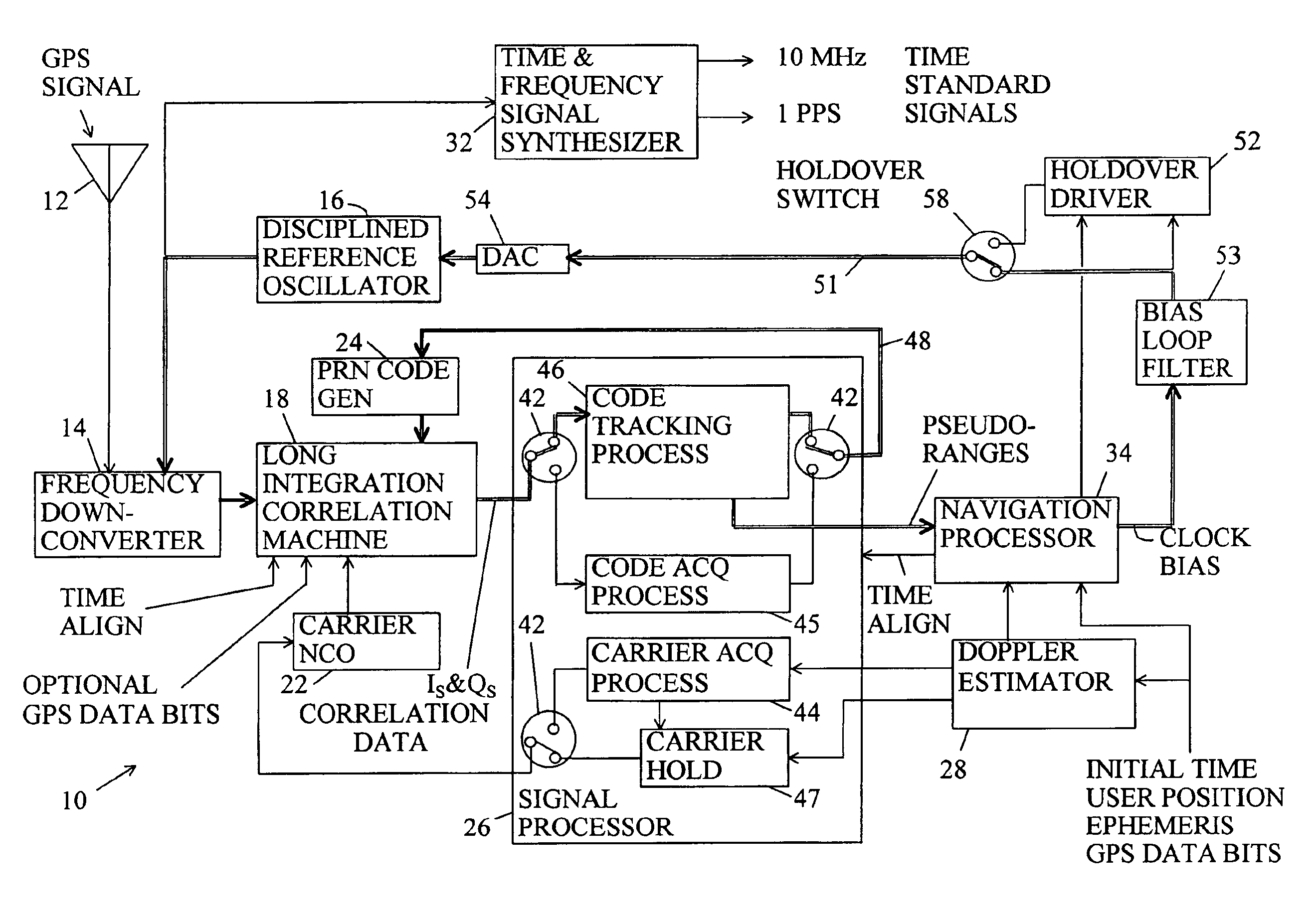
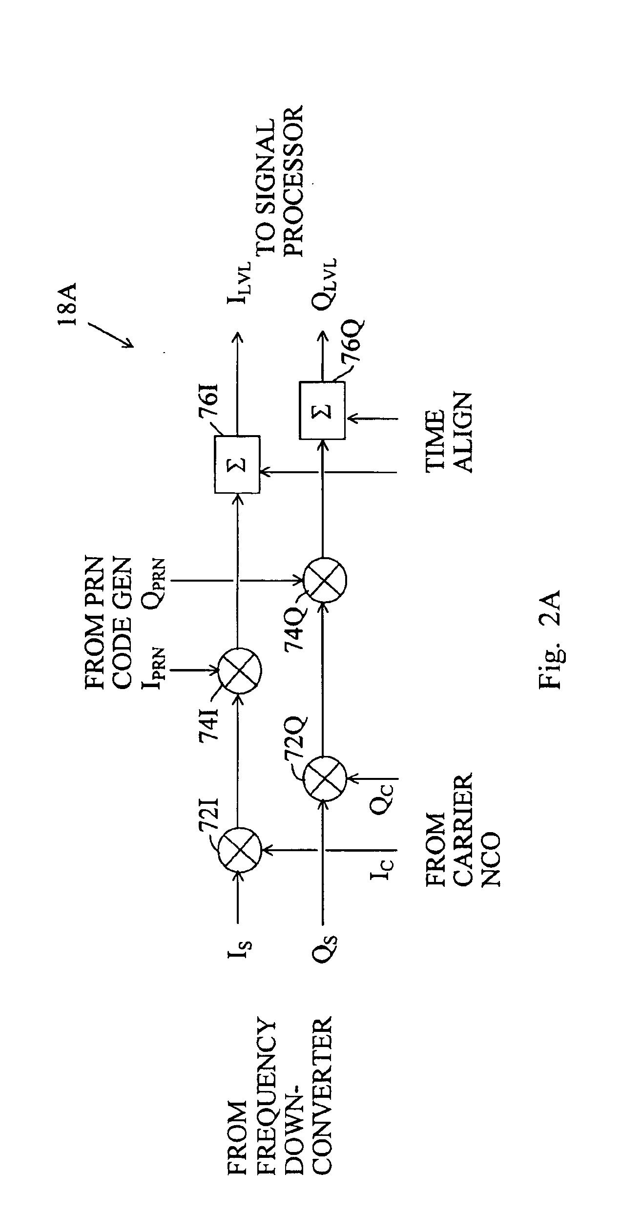
Briefly, the indoor GPS clock of the present invention is a novel combination of features using a processing gain of greater than 13 dB for acquiring and tracking low level GPS signals for providing a highly accurate GPS-based frequency. In a base coherent embodiment, the indoor GPS clock uses GPS data bit length (20 millisecond) coherent integrations for acquisition and tracking of low level GPS signals. In an extended coherent embodiment the indoor GPS clock uses coherent integration periods longer than the GPS bit data for acquisition of low level GPS signals. In a coherent-incoherent embodiment, the indoor GPS clock incoherently combines coherent integration periods for acquisition of low level GPS signals. The low level GPS signals are then tracked with carrier-less tracking using GPS data bit length coherent integration periods. A clock bias feedback loop provides feedback for disciplining frequency and time signals. A holdover driver compensates for drift in the disciplined frequency and time signals for at least several hours in the absence of the GPS signal.
An advantage of the present invention is that an accurate GPS-based frequency is provided within a building where GPS signal levels are lower than about −143 dBm.

Problems solved by technology

However, the accuracy for such time is limited by the cycle period of the local reference oscillator in the GPS receiver and any uncalibrated electrical length that the signal travels before it is used.
There are several GPS timing applications where these limitations are not acceptable.
It is well-known that GPS receivers do not function well within a building because the building attenuates the GPS signal to a level that is too low for acquisition and / or tracking.
However, there are certain circumstances where this is impractical.
Unfortunately, to date these techniques have not been applied in an indoor GPS clock that is capable of providing the frequency and time accuracies that are required.
One of the problems that must be resolved for low GPS signal levels is the problem of GPS signal carrier tracking.
However, below 27 dB-Hz C / N0 (−143 dBm referred to the antenna) and 24 dB-Hz C / N0 (−146 dBm referred to the antenna) typical GPS carrier phase and frequency lock loops, respectively, are not able to lock reliably.
However, techniques used in military receivers are not directly applicable to a high performance OPS clock because a military GPS receiver must operate in a high dynamic environment whereas a GPS clock is expected to operate in an environment that is stationary.

Method used


Image

  • Indoor GPS clock
  • Indoor GPS clock
  • Indoor GPS clock

Examples


Embodiment Construction

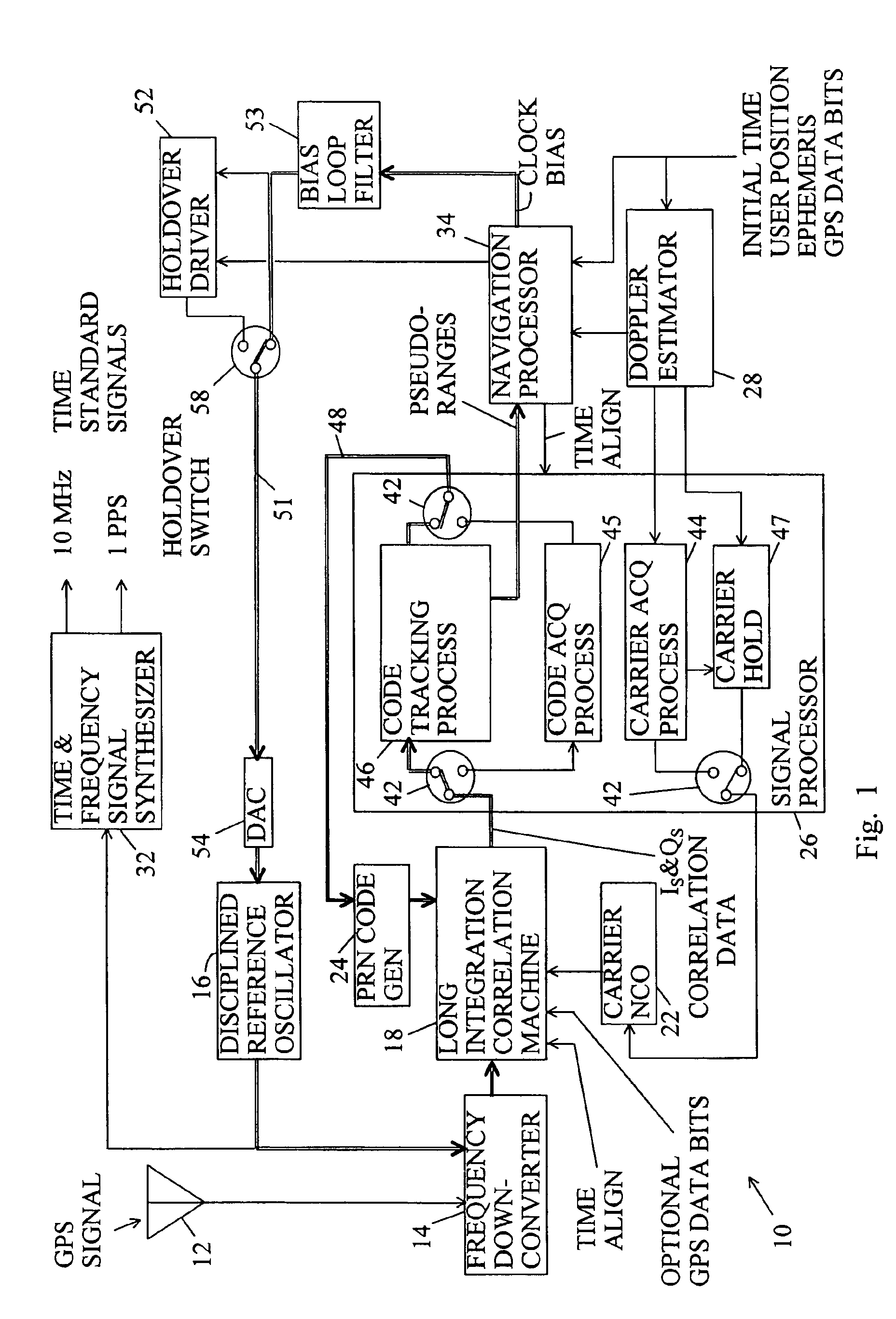
FIG. 1 is a block diagram of an indoor GPS clock of the present invention referred to with a reference number 10. It is expected that the indoor GPS clock 10 is maintained in a single user location for any one period of operation. To initialize the operation, the indoor GPS clock 10 receives information for an accurate user location, recent satellite ephemeris parameters, and time to within ±½ millisecond. In an exemplary case, the user location can be determined with survey techniques and the ephemeris parameters can be received and updated from a network connection.

The initial ±½ millisecond time can be determined by the indoor GPS clock 10 itself by operating first outdoors in the manner of a conventional GPS receiver. The indoor GPS clock 10 is then carried indoors to its user location. Or, when one strong GPS signal is available, for example from a pseudolite or a GPS satellite with line of sight through a window, the indoor GPS clock 10 can determine the initial ±½ millisecond...


PUM


Abstract

An indoor GPS clock using GPS signals lower that −143 dBm for issuing disciplined frequency and time standard signals. The indoor GPS clock includes a correlation machine using long integration periods for enabling the indoor GPS clock to operate with low signal levels; a carrier-less tracking loop for tracking the low level signals without carrier offset feedback, a clock bias loop for providing clock bias feedback; and a reference oscillator using the clock bias feedback for providing disciplined frequency and time signals having greater accuracy than is available in conventional GPS positioning receivers. The indoor GPS clock also includes a holdover driver providing compensation for predicted drift in clock bias error for disciplining the reference oscillator for several hours when the GPS signal is no longer being received.

Description

BACKGROUND OF THE INVENTION1. Field of the InventionThe invention relates generally to GPS clocks and more particularly to an indoor GPS clock using long integration periods for acquiring and tracking GPS signals lower than about −143 dBm and providing disciplined frequency and time standard signals.2. Description of the Prior ArtConventional GPS positioning receivers provide GPS-based time as a byproduct of the resolution of a three dimensional GPS-based location. Typically, this time is issued in the form of a data packet that identifies the GPS-based times of the pulses of a one pulse per second (1 PPS) output signal. However, the accuracy for such time is limited by the cycle period of the local reference oscillator in the GPS receiver and any uncalibrated electrical length that the signal travels before it is used. There are several GPS timing applications where these limitations are not acceptable. Therefore, GPS timing applications commonly require a higher frequency signal, ...

Claims


Application Information

Patent Timeline
IPC IPC(8): G01S1/00G01S19/25
CPCG01S19/29G01S19/246
Inventor YU, YIMING
Owner TRIMBLE NAVIGATION LTD
Learn More