Response waveform synthesis method and apparatus

a waveform and response technology, applied in the field of response waveform synthesis methods and apparatuses, can solve problems such as unnatural sound and unwanted noise, and achieve the effect of accurately reproducing the frequency characteristics of the original analyzed band

Inactive Publication Date: 2007-08-09
YAMAHA CORP
View PDF14 Cites 21 Cited by
  • Summary
  • Abstract
  • Description
  • Claims
  • Application Information

AI Technical Summary

Benefits of technology

[0010]According to the present invention, a synthesized band is set for each one or plurality of the analyzed bands without the frequency characteristic determined for each of the analyzed bands being used directly as-is, and a time-axial waveform is determined for each of the synthesized bands. Thus, the present invention can synthesize a smooth response waveform and thereby determine a non-discontinuous waveform on the basis of the frequency characteristics obtained by dividing the audio frequency bands into the plurality of partial (analyzed) bands.
[0011]Preferably, the inverse FFT step uses the frequency characteristics, determined for the individual analyzed bands (0−n) divided from the audio frequency range, to determine the time-axial response waveform for each of the synthesized bands i (i=1, 2, . . . , n) having a frequency band of the (i−1)-th analyzed band and a frequency band of the i-th analyzed band, and the additive synthesis step adds together the response waveforms of the synthesized bands i (i=1, 2, . . . , n) determined by the inverse FFT step, to thereby provide the response waveform for the whole of the audio frequency range. Thus, by using a same analyzed band i for adjoining i-th and (i+1)-th synthesized bands in an overlapping manner, the present invention can synthesize a smooth response waveform, without involving discrete characteristics in boundary regions between the bands even when the response waveform is determined per band.
[0012]Preferably, the inverse FFT step determines the response waveform for each of the synthesized bands i (i=1, 2, 3, . . . , n), using a frequency characteristic value obtained by multiplying a portion of the synthesized band, corresponding to the (i−1)-th analyzed band, by a sine square function (sin2 θ) as a rise portion of the waveform and a frequency characteristic value obtained by multiplying a portion of the synthesized band, corresponding to the i-th analyzed band, by a cosine square function (cos2θ) as a fall portion of the waveform. Because sin2θ+cos2 θ=1, even when the same analyzed band i is used for the adjoining i-th and (i+1)-th synthesized bands in an overlapping manner, the present invention can accurately reproduce frequency characteristics of the original analyzed band by additively synthesizing the response waveforms of the individual synthesized bands.
[0014]Preferably, the response waveform synthesis apparatus further comprises: a characteristic storage section storing respective characteristics of a plurality of types of speakers; a speaker selection assistance section that selects selectable speaker candidates on the basis of information of a shape of a room where speakers are to be positioned; a speaker selection section that receives selection operation for selecting one speaker from among the selectable speaker candidates; a speaker installation angle optimization section that, on the basis of a characteristic of the speaker selected via the speaker selection section, determines such an installing orientation of the speaker as to minimize variation in sound level at individual positions of a sound receiving surface of the room; and a frequency characteristic calculation section that calculates, for each of the plurality of analyzed bands divided from the audio frequency range, a frequency characteristic at a predetermined position of the room on the basis of the information of the shape of the room and the installing orientation of the speaker determined by the speaker installation angle optimization section. Here, the frequency characteristic storage section stores the frequency characteristic calculated by the frequency characteristic calculation section for each of the analyzed bands. Such arrangements can simulate sounds produced through a designed speaker arrangement. As a result, it is possible to implement an improved acoustic-designing assistance apparatus or method, by applying the response waveform synthesis technique of the present invention.

Problems solved by technology

However, if frequency characteristics obtained from the plurality of partial frequency bands are merely added together after being subjected to inverse FFT transformation independently of each other, there would arise discontinuous or discrete points in the frequency characteristics, which tends to cause unwanted noise and unnatural sound.

Method used


Image

  • Response waveform synthesis method and apparatus
  • Response waveform synthesis method and apparatus
  • Response waveform synthesis method and apparatus

Examples


Embodiment Construction

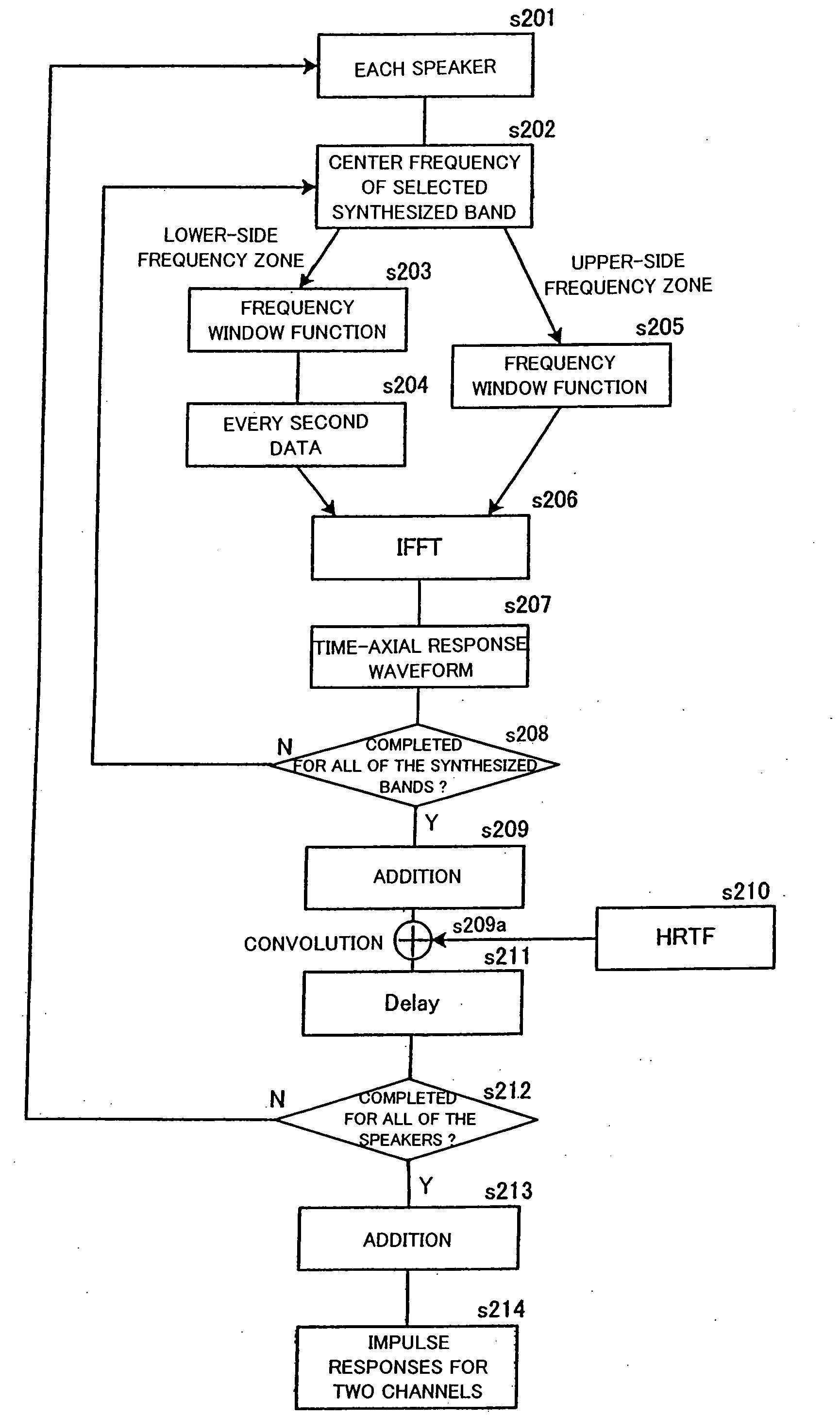
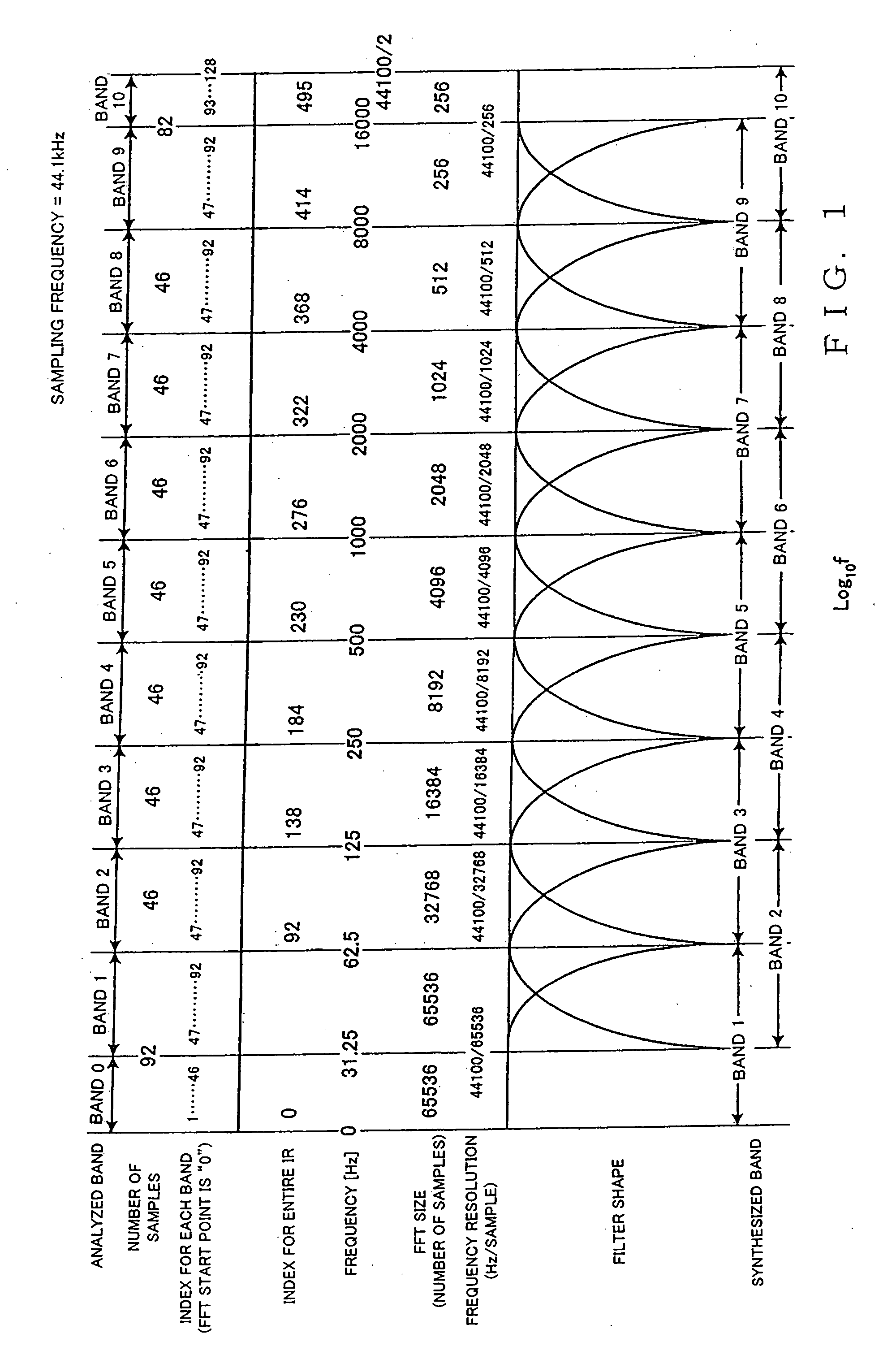
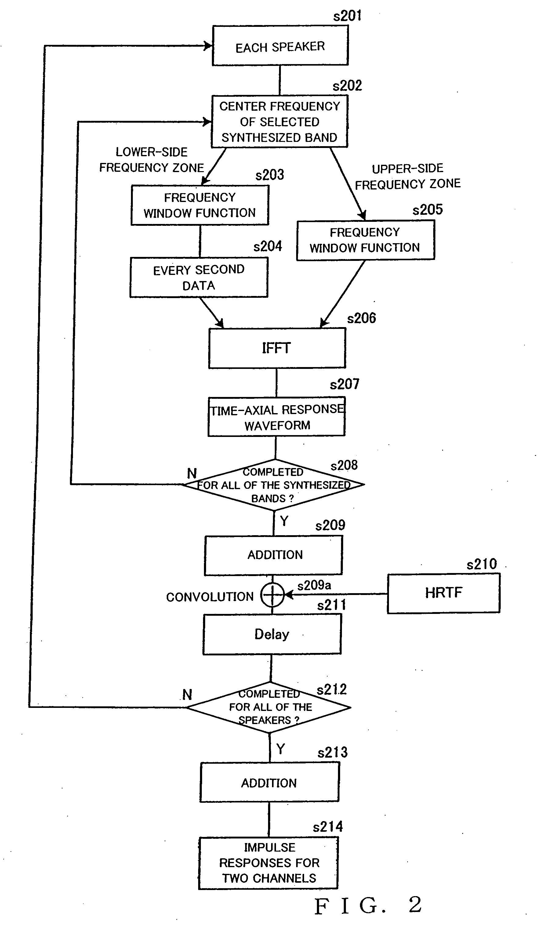
[0035]First, a description will be given about a response waveform synthesis method in accordance with an embodiment of the present invention. FIG. 1 is a diagram explanatory of the response waveform synthesis method which generally comprises dividing a predetermined audio frequency range (e.g., 0 Hz-22050 Hz) into a plurality of partial frequency bands (hereinafter referred to as “analyzed bands”) and then synthesizing a time-domain impulse response waveform of the entire audio frequency range on the basis of given frequency characteristics determined for each of the analyzed bands. In the illustrated example of FIG. 1, it is assumed that the sampling frequency of an audio signal processing system in question is 44.1 kHz and thus the upper limit of the audio frequency range is half of the 44.1 kHz sampling frequency, i.e. 22050 Hz. Therefore, if the sampling frequency of the audio signal processing system varies, the predetermined audio frequency range too varies.

[0036]In this case...


PUM


Abstract

Using frequency characteristics determined for individual ones of a plurality of analyzed bands of a predetermined audio frequency range with frequency resolution that becomes finer in order of lowering frequencies of the analyzed bands, a synthesized band is set for each one or for each plurality of the analyzed bands, and then a time-axial response waveform is determined for each of the synthesized bands. The response waveforms of the synthesized bands are then added together to thereby provide a response waveform for the whole of the audio frequency range.

Description

BACKGROUND OF THE INVENTION[0001]The present invention relates generally to a response waveform synthesis method and apparatus for synthesizing a time-axial impulse response waveform on the basis of acoustic characteristics in the frequency domain, an acoustic-designing assistance apparatus and method using the response waveform synthesis method, and a storage medium storing an acoustic-designing assistance program.[0002]For installation of a speaker system in a hall, event site or other room (or acoustic facility), it has heretofore been conventional for an audio engineer or designer to select a suitable speaker system on the basis of a shape, size, etc. of the room (or acoustic facility) and then design a position and orientation in which the selected speaker system is to be installed and equalizer characteristics, etc. of the speaker system to be installed.[0003]Because the designing work requires skill and cumbersome calculations, there have so far been proposed various acoustic...

Claims


Application Information

Patent Timeline
IPC IPC(8): G10L21/00
CPCH04R2205/024H04S2420/13H04S7/40H04S7/305G10K15/00G11B20/10
Inventor MIYAZAKI, HIDEO
Owner YAMAHA CORP
Why Eureka
Try Eureka